
Owner manual

Page 34
Voyager User’s Manual - The Components
Page 35
Voyager User’s Manual - The Components
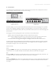
G – The LFO/Sample and Hold Section
The Voyager has a dedicated Low Frequency Oscillator (LFO) and Sample and Hold (S+H) function. The
LFO produces triangle and square waves that oscillate from .2 to 50 Hz. Both the triangle and square wave
outputs can be selected as modulation sources in the Mod Busses.
For the Sample and Hold circuit, the LFO’s square wave is used
as the S+H Trigger input, while the Voyager’s Noise source is used
for the S+H Input signal. For each positive-going cycle of the LFO
square wave, the voltage at the input of the S+H circuit is sampled
and held until the next cycle. Since the sample source is Noise (a
random signal), the voltage that appears at the output of the S+H
circuit is a random voltage that changes in time with the LFO.
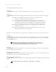
The Voyager’s CV Interface jacks (on the back panel of the Voyager
keyboard, or on the RME’s VX-352 CV Expander) allow additional
exibility with the Sample and Hold circuit. For example, if a plug
is inserted into the S+H Gate input, it will disconnect the LFO
trigger; an external gate signal can then be used to trigger the S+H
circuit. Similarly, a plug inserted into the S+H Input jack disconnects
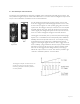
the Noise source from the S+H input. In this circumstance when
the S+H circuit is triggered, the voltage at the tip of the plug is
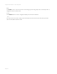
held at the output of the S+H circuit. This makes it possible to get
“staircase” modulation patterns. as shown below.
Voyager
Keyboard
Voyager
RME
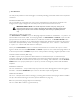
The Voyager’s Sample and Hold circuit can
create more than just random signals –
interesting stepped modulation patterns
are also possible.