© 2011, Moog Videolarm, Inc. All Rights Reserved Deputy2 Customizable Vandal-Resistant City Surveillance System www.videolarm.com Installation and Operation Instructions for the following models: D2BW1 Deputy2 Box with wall mount, support for up to 3 cameras. 110Vac input surge protection, H&B system and 24Vac output to the camera.
IMPORTANT SAFEGUARDS 1 Read these instructions. 2 Keep these instructions. 3 Heed all warnings 4 Follow all instructions. 5 Do not use this apparatus near water. 6 Clean only with damp cloth. 7 Do not block any of the ventilation openings. Install in accordance with the CAUTION RISK OF ELECTRIC SHOCK DO NOT OPEN manufacturers instructions. 8 9 SAFETY PRECAUTIONS Cable Runs- All cable runs must be within permissible distance.
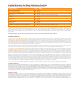
Limited Warranty for Moog Videolarm Products Moog Videolarm warrants these products to be free from defects in material or workmanship as follows: PRODUCT CATEGORY PARTS \ LABOR All Enclosures and Electronics* Five Poles/PolEvators™/CamEvator Three (3) Years Warrior Series™/Q-View™/IR Illuminators Five (5) Years SView Series™ Five (5) Years **6 months if used in auto scan/tour operation Controllers Five (5) Years Power Supplies Five (5) Years EcoKit Three (3) Years Accessory Brackets F
! Electrical & Mechanical Specifications Deputy2 Power 120 VAC Content of Box (X) 4 English Energía 120 VAC Español Puissance 120 VAC Français Energie 120 VAC Deutsch Poder 120 VAC Portuguese Alimentazione 120 VAC Italiano Note: Additional products may be included based around your purchase order
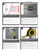
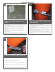
Pole Mount Assembly 2 1 Thread one retainer extrusion at the end of steel band, allowing 1” (254mm) of band out. Beveled end of extrusion to be out.
Pole Mount Assembly Continued • • • • • 5 6 Thread mounting hardware and additional retainer extrusion at opposite end of steel band. Refer to Block 1 and 2 for instructions. Place assembly around pole at desired mounting location. Insert bolt through retainer extrusions. Head of bolt needs to lock into end of retainer. Rosca de montaje de hardware adicional y anticipo de extrusión en el extremo opuesto de la banda de acero. Consulte a Bloque 1 y 2 para obtener instrucciones.
Pole Mount Assembly Continued 8 Installation is complete when nut is tight / secure and all slack has been removed from steel band. • La instalación es completa cuando es apretado la tuerca / garantizar la seguridad de todos y la atonía se ha eliminado de la banda de acero. • L'installation est terminée lorsque l'écrou est serré, sécurité et tous les mou a été retiré de la bande d'acier. • De installatie is volledig wanneer moer is strak / beveiligde en alle speling verwijderd is van staal-band.
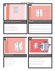
Wall Mount Assembly Continued 10 Place the mounting plate against the wall 11 Attach with (4) anchor bolts, (4) lock washers, and (4) flat washers • Fijación con (4) los pernos de ancla, (4) arandelas de cerradura, y (4) arandelas planas • Coloque la pletina contra la pared • Placez le plat de support contre le mur • Setzen Sie die Montageplatte gegen die Wand • Coloc a placa de montagem de encontro à parede • Disponga il giunto di supporto contro la parete 12 Tighten all bolts securely • Apr
Wall Mount Assembly 14 Align the mounting holes • Alinee los agujeros de montaje • Alignez les trous de montage • Richten Sie die Entlüftungslöcher aus • Alinhe os furos de montagem • Allini i fori di montaggio 15 Hook the Deputy2 unit onto the top of the mounting plate • Enganche la unidad Deputy2 sobre la tapa de la pletina • Accrochez l'unité Deputy2 sur le dessus du plat de support • Spannen Sie die Maßeinheit Deputy2 auf die Oberseite der Montageplatte an • Enganche a unidade Deputy2 na part
18 Completely tighten all four (4) bolts • Apriete totalmente los cuatro (4) pernos • Serrez complètement chacun des quatre (4) boulons • Ziehen Sie vollständig alle vier (4) Schraubbolzen fest • Aperte completamente todos os quatro (4) parafusos • Completamente stringa tutti e quattro le (4) bulloni 19 There are (2) water tight 3/4” conduit fittings at the rear of the box.
22 23 The Deputy2 can be customized with several cameras and features With an RM7 (see steps 26-31) • El Deputy2 se puede modificar para requisitos particulares con varias cámaras y características • Con un RM7 (26-31) • Le Deputy2 peut être adapté aux besoins du client avec plusieurs appareils-photo et configurations • Avec un RM7 (26-31) • Das Deputy2 kann mit einigen Kameras und Eigenschaften besonders angefertigt werden • Wit einem RM7 (26-31) • O Deputy2 pode ser personalizado com divers
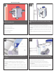
26 27 RM7 installation Remove cover plate and gasket from the bottom of the unit • Instalación RM7 • Quite la tapadera y la junta de la parte inferior de la unidad • Installation RM7 • Enlevez le couvercle et la garniture du fond de l'unité • Installation RM7 • Entfernen Sie Deckplatte und Dichtung von der Unterseite der Maßeinheit • A instalação RM7 • Installazione RM7 28 Place the RM7 housing into the unit oriented as shown • Coloque la cubierta RM7 en la unidad orientada como se muestra • Pla
30 31 Attach the trim ring/dome assembly Remove the cover plate to install the camera mounts • Ate el anillo del ajuste/el montaje de la bóveda • Quite la tapadera para instalar los montajes de cámara • Attachez l'anneau d'équilibre/dôme • Enlevez le couvercle pour installer les montures de caméra • Bringen Sie den Ordnungsring/die Haube an • Entfernen Sie die Deckplatte, um die Kameraeinfassungen anzubringen • Una o anel da guarnição/conjunto da abóbada • Remova a placa de tampa para instalar as
34 English • Open packet assembly. • Special ⅜” bolts are provided and designed to mount either the WM20G or the WM10 (Standard Fusion Dome and Rugged Housing wall mount bracket) to the Power box. • Assemble wall mount bracket and housing as shown in the next block. • Push the cable assembly connectors through either of the (2) holes provided. Español • Abra el montaje de paquete.
37 The (right) side electronics layout including optional Battery backup installation • La disposición lateral (correcta) de la electrónica incluyendo la instalación opcional del respaldo de batería • (La bonne) disposition latérale de l'électronique comprenant l'installation facultative de support de batterie • Der (rechte) seitliche Elektronikplan einschließlich wahlweise freigestellte Batterieaushilfsinstallation • A disposição lateral (direita) da eletrônica que inclui a instalação opcional do apoio de
40 OUTPUT: 24VAC (Heater) 24VAC (Camera) Auxiliary 24VAC output connection (not fused) Camera and heater/blower connection. Camera fused with 1 A resettable fuse. Heater fused with 4 A resettable fuses. The Deputy 2 unit is supplied with three camera power control boards. These boards will convert the 120Vac input voltage down to 24Vac. It will also distribute the 24Vac to the camera and the heater/blowers La unidad del diputado 2 se suministra tres tableros de control de energía de la cámara.
41 42 Wiring Instructions RJ45 BNC (Large) Power (Small) Alarms Wiring Color Code Power and Control Inputs AFTER CAMERA INSTALLATION Make inside housing wiring connections following Chart B below.
(2) Black Lead from Flashing Button 45 44 Transformer for light kit, Mount the 24 VAC/24 VDC transformer to the side panel with double sided tape • Realice el cableado según lo indicado Black Lead from light transformer Black , White and Red Lead from Beacon Red Lead from light transformer • Exécutez le câblage comme indiqué Perform the wiring as indicated • Führen Sie die Verdrahtung durch, wie angezeigt • Realice el cableado según lo indicado • Execute a fiação como indicado • Effettui i colleg
Replacement Parts List Deputy2
Replacement Parts List Deputy2
Replacement Parts List Deputy2 Part Drawing # Description QTY
Product Registration/Warranty Thank you for choosing Moog Videolarm. We value your patronage and are solely committed to providing you with the highest quality products available and superior customer service. Should a problem arise, rest assure that Moog Videolarm stands behind its products by offering impressive warranty plans: 3 Years on all Housings, Poles, Power Supplies, and Accessories and 5 Years on camera systems (SView, QView, Warriors), and InfraRed Illuminators.