© 2009, Videolarm, Inc. All Rights Reserved RM7 Vandal-Resistant Recessed Ceiling Dome Housing www.videolarm.
IMPORTANT SAFEGUARDS 1 Read these instructions. 2 Keep these instructions. 3 Heed all warnings 4 Follow all instructions. 5 Do not use this apparatus near water. 6 Clean only with damp cloth. 7 Do not block any of the ventilation openings. Install in accordance with the SAFETY PRECAUTIONS CAUTION RISK OF ELECTRIC SHOCK DO NOT OPEN manufacturers instructions. 8 Cable Runs- All cable runs must be within permissible distance.
LIMITED WARRANTY FOR VIDEOLARM INC. PRODUCTS VIDEOLARM INC. warrants this Product to be free from defectsin material or workmanship,as follows: PRODUCTCATEGORY PARTS LABOR Five (5) Years VIDEOLARM be(3) free from defects in material follows: Pan/TiltsINC.
! English Español Electrical Specifications Power 24VAC Class 2 Only 24 VAC 1.8 Amps 54 Watts Total Power: 54 Watts Accessories: Camera Power: Tools Required: RM7C2N RM7C2 (OUTDOOR ONLY) Heater: 25 Watts/Blower: 1 Watt 28 Watts .100” Flat Head Screwdriver Phillips Head Screwdriver Note: IRM7CN includes no accessories 24 VAC 1.
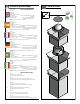
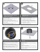
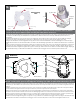
1 2 10.375” A box cutter or jigsaw can be used for cutting the circle. Using the provided template, mark the ceiling tile for the cutout. • Con la plantilla proporcionada, cortar el azulejo del techo para el agujero. • En utilisant le calibre fourni, marquez la tuile de plafond pour le coupe-circuit. • Mit der zur Verfügung gestellten Schablone kennzeichnen Sie die Decke Fliese für den Ausschnitt. • Usando o molde fornecido, marque a telha do teto para o entalhe.
5 6 Connect the flex conduit to the housing. • Conecte el conducto de la flexión con la cubierta. • Reliez le conduit de câble au logement. • Schließen Sie das Flexrohr an das Gehäuse an. • Conecte a canalização do cabo flexível à carcaça. • Colleghi il condotto della flessione all'alloggiamento. 7 Add the safety wire to the flex conduit or continue to the next step. • Agregue el alambre de seguridad al conducto de la flexión o continúe al paso siguiente.
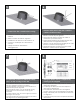
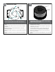
9 10 Green Yellow Orange ,5 22 Accessory Power ,75 20 1,0 18 1,5 16 2,5 14 4 12 6 10 MM2 AWG Camera Power Red Camera = red & orange wires to terminal Heater/Blower = yellow & green wires to terminal • Cámara fotográfica = alambres rojos y anaranjados al terminal Heater/Blower = alambres del amarillo y del verde al terminal • Appareil-photo = fils rouges et oranges à la borne Heater/Blower = fils de jaune et de vert à la borne • Kamera = rote u.
13 14 beamthe angle may bescrews adjusted on the bttom Secure dome with already inothe dome. the unit. • Asegure la bóveda con los tornillos ya en la bóveda. • Fixez le dôme avec des vis déjà dans le dôme. • Sichern Sie die Haube mit Schrauben bereits in der Haube. • Fixe a abóbada com parafusos já na abóbada. • Fissi la cupola con le viti già nella cupola. 15 17 The security screws provided can also be used to attach the dome.
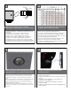
16 18 Axis 214 Mounting Hole 3026 Mounting Plate (3) #8 x 3/8” Captive Screw (52mm) 2" Mounting Hole Mounting Hole Install the camera to the mounting plate using (3) 3mm x 12mm bolts and lock washers. Place (3) #8x3/8” screws on the spacers and line up the mounting slots. Slide plate in and secure. • Instale la cámara fotográfica a la placa de montaje usando (3) los pernos de 3m m x de 12m m y las arandelas de cerradura.
18 17 Axis 231D/232D Mounting Hole 18 19 AXIS 231-232D Tab Loosen Screw Mounting Hole Mounting Hole Use the (3) keyhole slots indicated above. Loosen the screw to the right of the tab by approximately (5) turns. • Utilice (3) las ranuras del ojo de la cerradura indicadas arriba. • Employez (3) les fentes de trou de la serrure indiquées ci-dessus. • Benutzen Sie die (3) Schlüssellochschlitze, die oben angezeigt werden. • Use (3) os entalhes do buraco da fechadura indicados acima.
20 19 Locking Screw Captive Screw Keyhole Slot (3) Locking Pins (3) #8 x 3/8” (13mm) ½" Position locking pins and locking screw over slots and turn clockwise; secure the screw. Place (3) #8x3/8” screws on the spacers and line up mounting slots. Slide on plate and camera then secure. • Coloque los pernos de fijación y el tornillo de fijación sobre ranuras y dé vuelta a la derecha; asegure el tornillo. Coloque los tornillos de (3) del # 8x3/8"en los espaciadores y las ranuras de montaje de la formación.
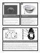
21 22 Open Screw Slots POWER 1 Camera Power (24VAC) Red 2 Camera Power (24VAC) Orange Cable Ties CONTROL RJ45 Ethernet Connector ALARMS 1 Alarm 1 Blue 2 Alarm 2 Violet 3 Alarm 3 Gray 4 Common White Captive Screw Complete thetypical wiring to of camera. Attach thelike camera the housing by sliding the (3) This is what the path illumination will look with the assembly setting at 30 to degrees. open screw slots over the screws in the housing; tighten the fasteners on the bracket.
25 Mounting Bracket ½" Now remove the mounting bracket and attach (4) 1/2” spacers (located in the packet that came with the housing) to the base bracket. • Ahora quite el soporte de montaje y una (4) los espaciadores del 1/2"(situados en el paquete que vino con la cubierta) al soporte bajo. • Maintenant enlevez le support et attachez (4) les entretoises de 1/2"(situées dans le paquet qui est venu avec le logement) à la parenthèse basse.
27 Thumb Screw Keyhole Slots Locking Screw Place quick release plate onto the bottom of the camera. Align the camera locking screws and the keyhole This isSlide what the typical path illumination will look likeuntil with the at 30 degrees. slots. camera intoof the keyhole slots thesetting locking buttons hit the end, and tighten the locking screw. • Coloque la placa rápida del lanzamiento sobre el fondo de la cámara fotográfica.
23 29 Canon VB-C50IR (13mm) ½" 2539 Mounting Plate Mounting Hole Captive Screw (26mm) 1" (52mm) 2" Mounting Hole Mount the camera to the 2539 plate using the provided hardware. Place (3) 8 x 32 x 3/8 Phillips head screws on the top of the spacer as shown above. Slide plate in and secure. • Monte la cámara fotográfica a la placa 2539 usando el hardware proporcionado. Coloque (3) 8 x 32 x 3/8 de los tornillos principales Phillips en la tapa del espaciador según lo demostrado arriba.
25 31 Elmo PTC-200C Mounting Hole 2539 Mounting Plate (13mm) ½" Captive Screw (3) 8 x 32 x 3/8 (26mm) 1" (52mm) 2" Mounting Hole Place the camera onto the quick release bracket using the (4) metric 3M Phillips head screws provided. Place the screws on the spacers. Slide on the plate and camera then secure. • Coloque la cámara fotográfica sobre el soporte rápido del lanzamiento usando (4) los tornillos principales los 3M Phillips métricos proporcionados. Coloque los tornillos en los espaciadores.
33 27 Elmo PTC-400C Mounting Hole 2539 Mounting Plate (13mm) ½" Quick release plate (26mm) 1" (52mm) 2" Mounting Hole Attach quick release bracket to mounting plate using (4) #8 screws and star washer. Complete assembly as shown, then secure camera to the quick release plate. • Una el soporte rápido del lanzamiento a la placa de montaje usando (4) los tornillos #8 y la arandela de la estrella. Termine a asamblea como cámara fotográfica demostrada, después segura a la placa rápida del lanzamiento.
29 35 JVC VN-C30U 2539 Mounting Plate (13mm) ½" (52mm) 2" Mounting Hole Remove the camera plate and mount to the bracket using the (3) metric 3M Phillips head screws. Reattach plate back to the camera. Place the screws on the spacers. Secure the plate and camera. • Quite la placa y el montaje de la cámara fotográfica al soporte usando (3) los tornillos principales los 3M Phillips métricos. Reate la placa de nuevo a la cámara fotográfica. Coloque los tornillos en los espaciadores.
37 31 JVC VN-C655U (13mm) ½" Mounting Hole 2630 Mounting Plate (26mm) 1" Place the camera on the bracket with the (4) phillips head screws. Use (4) 1” spacers and (4) 1/2” spacers provided. Place the screws on the spacers. Slide on the plate and camera then secure. • Coloque la cámara fotográfica en el soporte con (4) los tornillos principales Phillips. Utilice (4) los espaciadores del 1"y (4) 1/2" spacers proporcionados. Coloque los tornillos en los espaciadores.
33 39 Pixord 261/262 (13mm) ½" Mounting Hole 2630 Mounting Plate Install camera to the bracket with (3) 8x32x.5” flat head screws, nuts and washers. Place (3) 8x32x3/8”screws on the spacers. Slide on the plate and camera then secure. • Instale la cámara fotográfica al soporte con (3) los tornillos, las tuercas y las arandelas principales el 8x32x.5"planos. Coloque (3) 8x32x3/8"screws en los espaciadores. Resbale en la placa y la cámara fotográfica entonces seguras.
41 35 Sony SNCRZ30 (52mm) 2" 2539 Mounting Plate Mounting Hole Attach bracket with (1) 1/4x20 bolt, washer and lock washer. Place (3) 8x32x3/8”screws on the spacers. Slide on the plate and camera then secure. • Una el soporte con (1) el perno 1/4x20, la arandela y la arandela de cerradura. Coloque (3) 8x32x3/8" screws en los espaciadores. Resbale en la placa y la cámara fotográfica entonces seguras. • Attachez la parenthèse avec (1) le boulon 1/4x20, la rondelle et la rondelle de freinage.
37 43 Toshiba IK-WB21A Mounting Hole (26mm) 1" (52mm) 2" 2539 Mounting Plate Mounting Hole Remove camera bracket and attach to the 2539 plate with (4) 8x32x3/8 bolts and star washers. Place (3) 8x32x3/8”screws on the spacers. Slide on the plate and camera then secure. • Quite el soporte de la cámara fotográfica y únalo a la placa 2539 con (4) los pernos 8x32x3/8 y las arandelas de la estrella. Place(3) 8x32x3/8"screws en los espaciadores. Resbale en la placa y la cámara fotográfica entonces seguras.
Product Registration/Warranty Thank you for choosing Videolarm. We value your patronage and are solely committed to providing you with only the highest quality products available with unmatched customer service levels that are second-to-none in the security industry.