© 2009, Videolarm, Inc. All Rights Reserved SM7CS-9, SM7C12S-9 SView™ Series www.videolarm.com Installation and Operation Instructions for the following models: CERTIFIED Before attempting to connect or operate this product, please read these instructions completely.
IMPORTANT SAFEGUARDS 1. Read Instructions - All the safety and operating instructions should be read before the unit is operated. 2. Retain Instructions - The safety and operating instructions should be retained for future reference. 3. Heed Warnings - All warnings on the unit and in the operating instructions should be adhered to. 4. Follow Instructions - All operating & user instructions should be followed. 5. Electrical Connections - Only a qualified electrician should make electrical connections. 6.
SM75C2N IP Ready Network Housing Outdoor vandal resistant surface mount ptz IP camera system that can be mount facing down or facing towards the sky. 23x zoom Day & night camera. MPEG-4 & MJPEG video compression format, Full D1. Clear dome, w/24Vac input, heater/blower ELECTRICAL SPECIFICATIONS (OUTDOOR ONLY): ! (SM7CS-9) Power 24Vac , Class 2 Only Dome Assembly - Clear or Tinted Do not Total Power: 72 watts Accessories (Heater/Blower): 52 watts Heater: 50 watts assembled and installed.
WIRING INSTRUCTIONS (OUTSIDE OF HOUSING) The unit is set up with (2) individual power inputs: 1. Accessory Power (yellow and green wire) 2. Camera Power (red and orange) RJ45 If you wish to provide a single power transformer it is recommended that: 1. Be certain that you know the total power consumption of the housing Heater (50 watts) + Blower (2 watts) + camera pan/tilt (28 watts). 2.
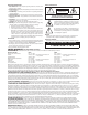
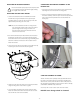
INSTALLING THE HOUSING ASSEMBLY: ! CONNECTING THE TRIM RING ASSEMBLY TO THE HOUSING TOP: Be sure the bracket is properly and securely mounted to a supporting structure capable of rigidly holding 1. Open the access door on the bottom of the wall mount by loosening the screw nearest the mounting plate. the weight of the entire unit. INSTALLING OPTIONAL WALL MOUNT 2. There is a safety lanyard that is attached to the inside of the dome assembly.
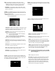
SETTING PROTOCOL FOR THE UNIT There are no user settings for protocol selection. The MR7CS-9™ will respond to Pelco D, Pelco P, or Videolarm VL422 protocol automatically (1 start bit, 1 stop bit, 8 data bits, no parity). Pattern A pattern is a programmed continuous path. The camera will follow this path repeatedly until the pattern is stopped. One pattern, with a maximum pattern time of 128 seconds, can be set.
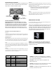
TEMP - This displays the temperature sensor data on the tilt board. Press "zoom in" to turn this on, "zoom out" to turn it off. NOTE: This reading will be higher than the actual ambient temperature in the dome. This is for diagnostic use only. ZONES - Up to 16 zones may be selected, each zone has a number of parameters associated with it. Pan Right to access Zones. "ZONE 1" will display. PRESSURE - This displays the pressure sensor data for units equipped with a pressure sensor.
SYSTEM INFO - Displays the Pan Version, Tilt Version, Current Pan Position and Current Tilt Position. Press AUTO TOUR and the tour of each preset will begin. When the tour reaches the preset designated for a dwell time of "0" the pattern will run. The pattern can be set for as many presets as desired, however, only one pattern can be recorded. EXIT - Pan left to exit the Main Menu. PRESETS - Allows the selection of the dwell times for each of the 64 presets.
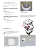
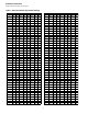
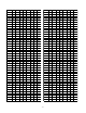
DIPSWITCH SETTINGS: Address Dip switch settings, refer to Table 1.
ADDRESS SW8 SW7 SW6 SW5 SW4 SW3 SW2 SW1 ADDRESS SW8 SW7 SW6 SW5 SW4 90 OFF ON OFF ON ON OFF ON OFF 135 ON OFF OFF OFF OFF ON ON ON 91 OFF ON OFF ON ON OFF ON ON 136 ON OFF OFF OFF ON OFF OFF OFF 92 OFF ON OFF ON ON ON OFF OFF 137 ON OFF OFF OFF ON OFF OFF ON 93 OFF ON OFF ON ON ON OFF ON 138 ON OFF OFF OFF ON OFF ON OFF 94 OFF ON OFF ON ON ON ON OFF 139 ON OFF OFF OFF ON OFF ON ON 95 OFF ON OFF ON O
ADDRESS SW8 SW7 SW6 SW5 SW4 SW3 SW2 SW1 ADDRESS SW8 SW7 SW6 SW5 SW4 SW3 SW2 180 ON OFF ON ON OFF ON OFF OFF 225 ON ON ON OFF OFF OFF OFF ON 181 ON OFF ON ON OFF ON OFF ON 226 ON ON ON OFF OFF OFF ON OFF 182 ON OFF ON ON OFF ON ON OFF 227 ON ON ON OFF OFF OFF ON ON 183 ON OFF ON ON OFF ON ON ON 228 ON ON ON OFF OFF ON OFF OFF 184 ON OFF ON ON ON OFF OFF OFF 229 ON ON ON OFF OFF ON OFF ON 185 ON OFF O
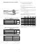
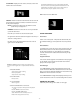
Exploded View for Replacement Parts 6 7 8 5 4 10 (1) 3 (1) 2 (2) 1 - 12 -
Exploded View for Replacement Parts (Surface Mount) 9 Replacement Parts List Part Number Description 1 RPSM7501 DOME SEAL 2 RPRH7502 LOWER TRIM RING 3 RC7T TINTED REPLACEMENT CAPSULE RC7C CLEAR REPLACEMENT CAPSULE 4 RPRH7503 DOME CLAMPING BRACKET 5 RPSM7511 HOUSING TOP 6 RPSM7512 MOUNTING HOLE CLOSURE 7 RPSM7513 CONDUIT HOLE CLOSURE 8 RPSN7514 WALL MOUNT BRACKET (OPTIONAL) 9 RPSM75040 HOUSING HARDWARE 10 RPPKH2090 HOUSING HARDWARE PACKET A N/S RPPKH2100 PACKET w/ ALLEN
Exploded View for Replacement Parts 5 2 6 12 1 7 3 4 8 10 9 11 Replacement Parts List Part No.
Exploded View for Replacement Parts 16 8 14 9 10 19 16 26 8 14 15 1 23 25 21 9 19 18 23 10 17 6 22 24 6 17 7 5 24 2 1 18 22 3 2 7 Replacement Parts List Part No. Description 1 RP6039mm1.
Product Registration/Warranty Thank you for choosing Videolarm. We value your patronage and are solely committed to providing you with only the highest quality products available with unmatched customer service levels that are second-to-none in the security industry.