
Operating instructions

Camera
Adjustment
Screw
Camera
Adjustment
Screw
Specifi cation Cat alog
Number Section
INSTRUCTIONS 5192 1a
MODEL: Outdoor Camera Housings
BMT10C
PRODUCT INSTRUCTIONS
2525 Park Central Blvd. • Decatur, GA 30035 • (770) 987-7550 • 800-554-1124 U.S. & Canada • Fax 800-826-0366 • www.videolarm.com
Figure 1
Figure 2
Figure 4
Figure 3
Figure 5
Figure 6
Figure 7
Figure 8
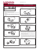
STANDARD IN STAL LA TION PROCEDURE
1. Carefully remove the housing from its box.
2. Prepare the installation site and gather the needed tools and
equipment.
3. Remove the (6) tamper resistant screws on the front of the
housing with the security tool provided in the installation packet
(Figure 1).
4. Remove the front end cap from the housing (Figure 2).
5. Loosen the camera adjustment screw (Figure 3).
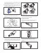
6. The cam era sled should now slide out of the housing
(Figure 4).
7. Remove the tilt brack et from the housing by re mov ing the (4)
hex head bolts that hold the mounting base to the housing
(Figure 5).
8. The ca ble strain reliefs that are provided in the kit can now be
screwed into the bot tom of the housing (Figure 6).
9. With appropriate hardware (not provided), attach the mount ing
brack et to the hous ing’s mount ing surface (Figure 7).
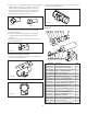
10. Run all of the incoming wiring through the 3/4" threaded coupling
located on the backside of the tilt bracket. You may also run the
wiring through the bottom of the tilt bracket. Should you chose
this option, plug the pipe coupling with a 3/4" pipe plug, available
at plumbing or hardware stores.
11. Run the incoming power wires through one of the strain reliefs,
and the video cable through the other. Reattach the
housing to
the tilt bracket with the (4) hex head bolts. The housing can be
mounted to the tilt bracket either right side up or upside down.
(Figure 8)
REVISION DATE: May 7, 2003