
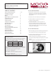
Specifications

- 2 -
CAMERA BRACKET SETUP (Figure 5)
Reattach the bracket assembly to the back box using the two
10-32 x 3/8" screws.
NOTE: For ceiling mount applications do not fully tighten
immediately.
Figure 2
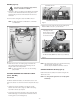
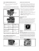
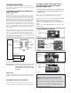
1. Connect the output of your Class 2 Power Supply to the terminal
connectors on the PC Board inside the housing. Refer to the
Troubleshooting section later in this instruction sheet for more
information.
2. Connect the incoming video cable to the BNC connector.
NOTE: For NVT Twisted Pair see Addendum 1, for IFS Fiber
see Addendum 2.
Terminal Connector
Positive
Negative
NOTE: The following instructions are for camera bracket setup,
camera focusing, and camera set-up.
The fi nal steps for installation follow these sections.
Use Class 2 Power only. Input voltage must be
between 12-28 VDC or 15-28 VAC.
WIRING (Figure 2)
Connected to
the Camera
Connect to
incoming video
BNC
Power
Board
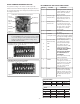
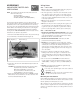
DESCRIPTION
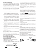
The Warrior Test Monitor Cable is a tool that allows users to view
video from cameras via a small on-site monitor. It's quick and easy to
use.
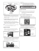
1. Using the security tool provided, loosen the four security
fasteners and remove the housing top. NOTE: The housing
top is held to the base by a lanyard.
2. Locate the power board on the inside of the housing. The Test
Monitor Cable plug is located beside the terminal block where
incoming power is connected (Figure 3).
Figure 3
Power Board
Terminal Connector
Test Monitor Cable plug
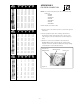
3. Plug the test monitor cable into the power board (Figure 4).
Attach the BNC connector to your test monitor.
Test Monitor Cable (NOTE: Your cable may look different)
Figure 4
The plug for the Test
Monitor Cable is polarity
protected and can only
be inserted one way.
OPTIONAL WARRIOR TEST MONITOR CABLE
(Part # - WSTMC)
3. Attach the back box to the double gang box installed in the
wall, carefully arranging wiring to prevent damage. Secure
using the 8-32 x 1/2" screws provided.
NOTE: In outdoor applications be sure to use the mounting
pads provided.