
Operating instructions

PRODUCT INSTRUCTIONS
REVISION DATE: 02-02-2009
81-IN5270 WARRIOR 9
WS9-50FIR
NOTE: THERE ARE NO USER SERVICEABLE PARTS INSIDE
THIS UNIT. OPENING THE WS9 HOUSING WILL VOID
THE WARRANTY.
STANDARD IN STAL LA TION PROCEDURE
INCLUDES MODEL: WS9
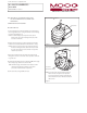
1. Select an appropriate location for the WS9 to be mounted. Place
the unit against the wall or ceiling and mark the center mounting
hole on the bracket (Figure 1).
NOTE: For additional support you may want to also place a
fastener in the slot on the mounting bracket. If so, mark
its location at this time.
2. Remove the unit and drill a hole for the appropriate mounting
hardware (not included). Mount the unit to the wall or ceiling.
NOTE: It may be necessary to remove the camera and housing
from the mounting bracket to attach the unit to the wall.
If so, the camera will need to be oriented correctly when
reattached (see below).
3. Run power and video wiring to the WS9. The exit hole for the
wiring will need to be as close to the unit as possible to eliminate
long cable runs.
4. Power for the WS9 must be from a regulated 12VDC power supply
with a voltage range between 10.8 and 13.2 DC.
NOTE: Transformer plug is female. Dimensions must be 2.1mm
I.D. and 5.5mm O.D., with a length of 9.53 to 12mm
(such as the Switchcraft S760 or equivalent)
5. Connect the video using the BNC connector.
NOTE: If you remove the camera from the bracket you
must reorient it correctly when it's replaced. A
sensor is located in the I.R. array surrounding the
camera window. This sensor indicates the bottom
of the camera.
Figure 1
Wa ll Mount Con guration
Center hole
Figure 2
Ceiling Mount Con
guration
I.R. Sensor
(bottom of camera)
© 2009, Videolarm, Inc. All Rights Reserved