MANUAL NO.
Introduction The owners portion of this manual, pages 1 through 11, provides introductory material to familiarize the owner with the features, specifications and initial set-up of the Minitmoog Synthesizer, Model 3Q0A, and the Satellite Synthesizer, Model 5330. The technical portion of this manual, pages 12 through 57, provides servicing,, replacement parts list and illustrations to enable a qualified technician to service and maintain the Minitmoog and Satellite Synthesizers.
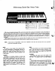
Minitmoog Controls SLIDE CONTROLS PANEL MODULATION CONTROLS GLIDE CONTROL SYNC, GLIDE POWER OFF-ON SWITCH INDICATOR LIGHT SOLO KEYBOARD VOLUME CONTROL SUSTAIN TABS FILTER CONTROLS TOUCH SENSE QUICK-SET VOICING TABS MODULATION TABS Before proceeding with Operation and Adjustment of your unit, please refer to page 10 for Connection Instructions. LEVEL ADJUST M u . e „ This rotary control (located on the back of the unit) sets the overall output level, or volume, of the unit.
Minitmoog Quick-Set Voice Tabs GUITAR-1 VIOLIN TAURUS With the unit connected and power ON, a sound can be heard when a note on the keyboard is struck, even though no voices are selected and all slide controls are set at "0" (except for the VOLUME control). The controls described herein will add and subtract from that sound in a multitude of combinations available for your exploration - shape it, change its attack and release, raise it, or lower it.
AIRES TAURUS This voice approximates that of a saxophone. With adjustment of other controls you will be able to vary the aa und through the characteristics of alto and tenor, barine, and bass sounds of the Taurus Synthesizer. we Banjo type sounds are provided with the hollow sound characteristic of this voice. In the lower registers it can simulate the plucked sound of the string bass, or bass violin.
MOD TREM (TREMULANT) This tab provides modulation of the harmonic content of the tone. The harmonic content, or timbre, is varied at a rate determined by the RATE control and with an intensity determined by the DEPTH control. This tab allows either vibrato or tremolo to be added to the tone as the pressure on the keys is increased. The NOTE: only if the MODULATION VIB or MODULATION TREM VIB and TREM can be used together.
FILTER CONTROLS SUMMARY Remember, the "Quick-Set" tabs establish an overall range of sound and the three Filter slide controls give you a wide selection and control within the limitations of that range. Try this: 1. Depress TRUMPET tab, and set the slide controls at "0". 4. Now do the same with the BRIGHTNESS control. The sound will range through cornet, trumpet, and flugelhorn characteristics. 2. Play a few notes on the keyboard. 3. Play again with various settings of the DECAY slide pot.
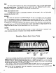
TUNE This rotary control (located on the back of the unit) provides a range of tuning which extends more than one-half octave. This flexibility can be used to tune your MOOG SATELLITE to other instruments, transpose to different keys, or even provide a glissando effect. POWER AND INDICATOR LIGHT An ON-OFF power switch is conveniently located on the front panel, with a red light which indicates when the power is ON.
MUTE BRASS BRIGHT REED "lows", moves to the "highs" and returns. Each time a With adjustment of other controls you will be able to vary the sound through the characteristics of alto and tenor, baritone, and even bass saxophone. This voice is a new version of the wah-wah effect. The sound approximates a double-acting wah-wah, .or "ooowah-ooo." It starts with an emphasis on the key is depressed the "ooo-wah-ooo" sound is pro duced. Try it in each octave.
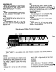
Satellite Modulation Tfrf RATE—' DEPTH REPEAT-* ' I UTREMULANT VIBRATO The four function tabs labeled MODULATION on the front of the unit provide a selection of modulation types. The two MODULATION slide controls on the slide control panel adjust the RATE and DEPTH of modulation. VIB (VIBRATO) This tab provides a frequency-modulation vibrato REP (REPEAT) The repeat tab affects only those "QUICK - SET" similar to the type used in electronic organs.
Satellite Slide Control Panel L EMPHASIS FILTER CONTROLS Once a "Quick-Set" tab voice selection is made, further refinement and adjustment of that voice may be made by using the three slide controls labeled FILTER. CONTOUR This controls the speed of the timbre change associated with the onset of the voice, and/or the timbre change associated with the release of that voice.
Accessory and Connections For operation, the Synthesizer unit should be placed on a horizontal surface in a location which will not interfere with its operation. NOTE: Avoid placement in close proximity to electronic circuitry, as on the top of some electronic organs, because excessive hum may result. LO-LEVEL OUTPUT 130 millivolts RMS), Phone Jack designed for use with Guitar Amplifier, P.A. Systems, etc. HI-LEVEL OUTPUT (1 volt RMS), RCA Phono Jack designed for use with Electronic Organs.
Care of Your Synthesizers Your MOOG Synthesizer is carefully designed to give you maximum pleasure and satisfaction with a minimum of care. Following these tips on the care of your Synthesizer will help keep it "showroom new." ■ LOCATION As with any electronic instrument, avoid placement in direct or prolonged sunlight. Normal variation of temper ature will not affect the tuning or electronic circuitry of the synthesizer.
TECHNICAL SERVICE SECTION for MINITMOOG/ SATELLTE Minitmoog Model 300A Satellite Model 5330 12
CONTENTS SECTION 1 INTRODUCTION 2 CIRCUIT DESCRIPTION 2.1 GENERAL 2.2 POWER SUPPLY 2.3 KEYBOARD CIRCUIT 2.4 2.5 2.6 2.7 2.8 2.9 2.10 2.11 3 PAGE 15 15 15 15 16 OSCILLATOR BAND PASS FILTER LOW PASS FILTER VOLTAGE CONTROLLED AMPLIFIER AMPLITUDE CONTOUR GENERATOR FILTER CONTOUR GENERATOR MODULATION OSCILLATOR TOUCH SENSOR 18 20 20 20 21 22 22 22 • DISASSEMBLY, VISUAL INSPECTION AND REASSEMBLY 4 3.1 3.2 3.3 DISASSEMBLY VISUAL INSPECTION PRINTED CIRCUIT BOARD REMOVAL. 3.
LIST OF ILLUSTRATIONS FIGURE 2-1 TITLE PAGE NO. Keyboard Trigger Voltage Waveforms 17 2-2 Emitter of Q46 18 2-3 Synchronization of Oscillator B to Oscillator A 19 2-4 Emitter Voltage of Q35 21 2-5 Source Voltage of Q32 21 3-1 Minitmoog Printed Circuit Board Location (Inside View) 24 3-2 Minitmoog Cover and Printed Circuit Board Locations (Bottom Views) .... 24 4-1 Minimal Test Setup for Tuning 25 4-2 Two Channel Oscilloscope Test Setup for Tuning 26 4-3 Main Board No.
SECTION 1 INTRODUCTION This manual provides servicing and parts infor of which depends on which key is depressed. In mation for Minitmoog Synthesizer Model 300A and Satellite Synthesizer Model 5330, manufactured by Moog Music Inc., 2500 Walden Avenue, Buffalo, New York 14225. This manual was written basically for the Minitmoog Synthesizer which includes the addition, the keyboard produces a trigger voltage touch sensor board 4 and oscillator B board 5 not time a key is depressed.
developed across current sense resistor R2 limits the current. The negative power supply voltage regulator consists of IC2, Ql and associated components and adjusts its output to have the same magnitude as the regulated +9 volt output. No current limiting, other than that supplied by R8, is provided. 2.3 KEYBOARD CIRCUIT The keyboard circuit consists of IC3 thru IC7, IC9, IC10 and related circuitry. The keyboard contains a string of thirty-six 100-ohm resistors connected between pins A5 and A6.
DETAIL A ~+7V I—1ST KEY DOWN t2ND KEY DOWN JD KEY UP—I +4.5V IC 4 OUTPUT KEYBOARD CONTROL VOLTAGE 1ST KEY-] up OV -4.5V +7V DETAIL B OV IC 5 OUTPUT DC KEYBOARD DETECTOR -16V ■20 MSEC DETAIL C +9V 05 COLLECTOR TRIGGER PULSE OV -7V -12V 20 MSEC DETAIL D +9V 08 COLLECTOR DC TRIGGER OV DETAIL E +8V Q4 BASE KEYBOARD SAMPLE AND HOLD DRIVE DETAIL F +4.5V SOURCE OF Q51 SAMPLED KEYBOARD CONTROL VOLTAGE PREVIOUS NOTE OV -4.5V +8V DETAIL G -I I*— 1.5 MSEC + 1.
down since Q6 is fired by the negative going output pulse of IC5 coupled via C9, R192, R78 and D10. and 4 of IC11. The ratio of currents through these two transistors in IC11 is an exponential function of However, if the higher key is held and the lower key the voltage difference between their bases. The current is depressed or released, nothing will happen since the fed into pin 1 of IC11 is kept constant by IC21 which keyboard buss voltage remains constant.
of IC13. The control current applied to the input SYNC tab switch, the aB" PITCH control sweeps of IC13 from the resistor matrix determines the out the natural frequency of oscillator B over a range of put voltage of IC13. When the control current is more than four octaves. In this case, R505 shifts the zero, Q47 remains saturated throughout the entire pitch of oscillator B such that oscillators A and B are sawtooth cycle.
shunts varying proportions of oscillators A and B to ground. The values of resistors R522 thru R525 relative to the value of the A/B MIX control are set so that the signal power sum at pins Z and ZZ tends contour voltage applied to R116 and the keyboard to remain constant as the A/B MIX control is rotated. conducts, it becomes saturated and shorts out the The output at pin Z is the oscillator A signal applied keyboard voltage controlling the center frequency.
2.8 AMPLITUDE CONTOUR GENERATOR Of the two contour generators, the amplitude contour generator is the simplest, so it will be described first. This contour generator consists of Q34, Q35, difference between the bases of Q28 and Q29. Thus, since the decay time of an envelope is generally longer than the attack time, the voltage appearing at the source of Q32 has an attack time inversely proportional to the collector current of Q26.
2.9 FILTER CONTOUR GENERATOR The filter contour generator contains most of the rod on which a key bears when it is fully down (bottomed). Excess key pressure forces the rod to compress its foam rubber support pad causing the features of the amplitude contour generator. Q15 of the filter contour generator corresponds to Q35 of the amplitude contour generator, Q13 to Q34 and rod to come into more intimate contact with the Q12 to Q36.
The touch control output at pin G rises from 0 (as a result of pressing down harder upon a key), the voltage at the junction of R404 and R406 begins to to approximately +6 volts and sweeps the filters, both -i$e. Thus IC402, Q402, Q403 and related circuitry oscillators or just the second, oscillator depending on yrnPa dc restorer that keeps the voltage at the how the front panel touch sensor switches are set.
TOUCH SENS.OR BOARD NO. 4 "B" OSCILLATOR BOARD NO. 5 POWER SUPPLY BOARD NO. 2 MAIN BOARD NO. 1 MATRIX BOARD NO. 3 . (NOT VISIBLE) FIGURE 3-1 MINITMOOG PRINTED CIRCUIT BOARD LOCATIONS (INSIDE VIEW) RESISTOR MATRIX BOARD NO. 3 D CONNECTORS B CONNECTORS D CONNECTOR MAIN BOARD NO. 1 OSCILLATOR BOARD NO. 5 (MINITMOOG ONLY) e ©Do e © 0 CONNECTORS TOUCH SENSOR BOARD NO. 4 (MINITMOOG ONLY) \ POWER SUPPLY BOARD NO. 2 C.'.
c) Resistor Matrix Board No. 3 — Disconnect electrical connector, depress levers on 4 fastening devices and remove board with cable assembly attached. Jisconnect "D" connector on main board No. 1. d) Touch Sensor Board No. 4 — Disconnect electrical connector, remove 2 nuts and carefully lift board from instrument. L-bracket to rear of keyboard frame and carefully lift keyboard from chassis. 3.
FIGURE 4-2 TWO CHANNEL OSCILLOSCOPE TEST SETUP FOR TUNING should be used if a two channel oscilloscope is of oscillator board No. 5 and turn +9 volt adjust trimpot available. In the test setup of Figure 4-2, display R4 on main board No. 1 (Figure 4-3) until the +9 volt height and audio level are independent and it is not line is exactly +9.000 V ±10 mv. necessary to trigger the oscilloscope off of a composite b) Connect DVM across pins L (-) and K (+) of waveform.
of main board No. 1 and observe voltage drop d) Center the rear panel TUNE control, connect across keyboard. b) Adjust keyboard trimpot R79 (Figure 4-3) for wiper to ground, place 1 OCT tab switch down and a voltage indication of +9.000 V +10 mv. tom of R14, Figure 4-3) and ground. Adjust range connect DVM test leads between pin 6 of IC8 (bot trimpot R16 for an indication of 0.0000 +0.0001 V. 4.2.
NOTE Repeat paragraphs 4.2.7 and 4.2.8 several times as the adjustments interact, i.e., each time the scale is reset, the high frequency e) Set A/B MIX control to vertical so that the pitch of oscillators A and B may be compared. 4.2.12 OSCILLATOR B SCALE (Minitmoog Only) will go off frequency and vice versa. The process converges quickly so that both 1 OCT tab switch up adjustments can be accurately set. 2 OCT tab switch down "B" PITCH control full CCW 4.2.
c) Repeat paragraphs 4.2.12 and 4.2.13 several times as scale and high end adjustments interact. 4.2.14 OSCILLATOR B OCTAVE TRANSPOSITION (Minitmoog Only) 1 OCT tab switch down 4.3.2 SQUARE WAVE DUTY CYCLE a) Observe waveform at junction of R44 and R119 (Figure 4-3). b) Depress CLARINET (REED HOLLOW, Satellite) tab switch and adjust square wave adjust trimpot R47 for a symmetrical square wave as shown in Figure 4-6.
4.3.5 FILTER CONTOUR ATTACK AND DECAY TIMES a) Depress 1OCT tab switch. ^60-70. MSEC +3.7V. b) Depress MUTE (BRASS MUTE, Satellite) tab switch and observe filter contour at the source of Q20 (Figure 4-3) while repeatedly striking C key one octave from bottom of keyboard. c) Adjust filter decay and attack trimpots R98 and R105 until the filter contour matches the pattern KEY DOWN-* 0V- -20 MSEC shown in Figure 4-8.
SECTION 5 OPERATING CONTROLS, INDICATORS AND CONNECTORS Satellite Synthesizer panel marking differences are shown in parentheses. PANEL MARKING REF DESIG FILTER ATTACK (FILTER CONTOUR) Slide Control R7 FILTER DECAY R8 FUNCTION Controls amount of time it takes for the bright ness to reach a peak; 0 is the normal setting, -4 indicates the longest attack and +4 the shortest attack times.
OPERATING CONTROLS, INDICATORS AND CONNECTORS (Cont.
OPERATING CONTROLS, INDICATORS AND CONNECTORS {Cont.) PANEL MARKING REF DESIG FUNCTION SUST Tab Switch SW13 When depressed, allows note to die away more gradually after key is released. MUTE (BRASS MUTE) Tab Switch SW12 When depressed, approximates a "wah-wah" muted brass voice starting with an emphasis on the lows, moving to the highs and returning each time a key is depressed. When depressed, keyboard produces the sounds of a trumpet, trombone or tuba by depending on various other controls.
OPERATING CONTROLS, INDICATORS AND CONNECTORS (Cont.) SECTION 6 KEYBOARD MAINTENANCE AND ADJUSTMENT 6.1 CONTACTS 6.1.1 DIRTY CONTACTS CAUTION Do not touch J-wires or buss bar with bare fingers as salty, oily finger The J-wire switch contact to the buss bar may become dirty or corroded. If so, use ordinary rub bing alcohol (isopropanol) on a cotton swab to clean the contact area.
ward travel and white keys between 3/16 and 1/4 inch. If necessary, rebend by gently massaging the assembly and not on the key leveling tabs. The 5 studs are locked into position by 10 nuts on portion of the wire between the actuator and the either side of the keyboard frame. The sensor is attachment point. The contact must make before intentionally warped by the extreme end studs the key bottoms on the touch sensor assembly.
adjusting screws pass or at the end of the rod if the No. 6 screw touches the nylon. Repair these shorts by sticking a small piece of Scotch No. 156 the key contacts. In addition, check for a strand of 2 mil mylar tape over the area of the short. Burn bending pitch, the pitch drifts down at an objec a hole in the tape with a soldering iron for the adjusting screw.
SECTION 7 TROUBLESHOOTING GUIDE The procedures that follow generally apply to both Synthesizers except where the Oscillator Board 5 and Touch Sensor Board 4 are mentioned. These components are used only on the Minitmoog. An aid in control selection is presented in Section 5 indicating the different panel markings for identical controls.
TROUBLESHOOTING GUIDE (Cont.) SYMPTOM PROBABLE CAUSE 7.2 SOUND CHAIN Set the following controls as follows for all sound chain troubleshooting procedures. All tab switches up except VIOLIN tab switch down. All slide controls at zero position except VOLUME slide control at 10. All front panel rotary controls full counterclockwise position. A. B. No sound and POWER indicator light off. 1. No sound, POWER indicator light on and 9 volt power supplies 1. operating properly. 2. 115 VAC wiring faulty.
TROUBLESHOOTING GUIDE (Cont.) PROBABLE CAUSE SYMPTOM 7.2 SOUND CHAIN (Cont.) E. F. G. H. No oscillator B output, 1. IC501, IC502, Q501, Q502 or Q503 defective. oscillator A operating 2. Input wire to board No. 5 broken. properly. 3. 4. Resistor R501 broken. Connector pin M, R or P shorted. 5. IC11 defective. No oscillator A output, 1. IC12, Q43, Q44, Q45 or Q46 defective. oscillator B operating properly. 2. Open OSC A HI END trimpot. 3. Capacitor C38 shorted. No waveshaper output.
TROUBLESHOOTING GUIDE (Cont.
SECTION 8 MODIFICATIONS 8.1 1. Remove the touch sensor from the unit by SERVICE BULLETIN 802 removing the bottom cover and unscrewing four This Service Bulletin was issued and is included in this manual to avoid future maintenance because screws (Figure 8-1) to disassemble the unit to the extent shown in Figure 8-2. of defective or intermittent touch sensor bar. This condition occurs because of a chemical reaction between the foam and conductive nylon material. 2.
R EMOVE 5 NUTS ADJUSTMENT SCREW ; RIGHT SIDE FIGURE 8-2 MINITMOOG DISASSEMBLED 5. Apply two strips of double sided tape to completely recover the foam pad (Figure 8-5). wire around the two mounting holes and allow sufficient excess wire to extend beyond the right side of the bar to permit soldering the wire to the cable 30 6. Install a drain wire, No. 30 AWG gauge (No. •0 buss wire), generally centered along the length of che touch sensor bar.
FIGURE 8-4 SENSOR REMOVED FROM TOP SUPPORT 7. Install new conductive nylon. 9. Also wrap the end of the touch sensor bar with mylar tape at the point where the drain wire extends 8. Add mylar tape insulating pads over the nylon material at the two mounting holes (Figure 8-6). beyond the end of the bar (Figure 8-6) to prevent shorts after connection in the circuit.
10. Remove the snap fastener from the shield braid in the Minitmoog. 12. Mechanically reassemble the touch sensor bar in the reverse order of disassembly. NOTE 11. Install the touch sensor bar in the unit and solder the drain wire to the shield braid of the The drain wire should be positioned to the left side when reassembling the unit. interconnecting cable. V FIGURE 8-6 TOUCH SENSOR BAR REASSEMBLED 8.3 INSTALLATION OF NEW OR REBUILT TOUCH SENSOR BAR 1. Remove case. 5. Remove five mounting nuts.
SECTION 9 SELECTED REPLACEMENT PARTS LIST MINITMOOG AND SATELLITE MISCELLANEOUS SELECTED REPLACEMENT PARTS LIST 46
MAIN PRINTED CIRCUIT BOARD SELECTED REPLACEMENT PARTS LIST 47
MAIN PRINTED CIRCUIT BOARD SELECTED REPLACEMENT PARTS LIST (Continued) REF DESIG PART NUMBER DESCRIPTION CROSS REF NO. TRANSISTORS Q1 991-041062-001 86-5150-2 991-041052-001 86-5115-2 PNP, TIS93 Q2,Q4,Q6,Q7, Q9thruQ15, 017,025,026, Q27,Q31,Q34, Q35,Q36,Q43, 044,046,047, Q48.Q50 86-5149-2 PNP, 2N3906 Q3,Q5,O8, O16,Q19,Q21, 024,028,029, Q30,Q33,Q37 thru Q40.Q49 991-041051-001 86-5148-2 86-5124-2 NPN, 2N3904 020,032,041, Q42.
MINITMOOG TOUCH SENSOR BOARD NO. 4 SELECTED REPLACEMENT PARTS LIST MINITMOOG OSCILLATOR BOARD NO.
CONTROL BOARD (POWER SUPPLY) SELECTED REPLACEMENT PARTS LIST SECTION 10 BLOCK AND SCHEMATIC DIAGRAMS FIGURE 50 PAGE TITLE 10-1 Minitmoog Schematic Diagram 51 10-2 Minitmoog Block Diagram 52 10-3 Minitmoog Printed Circuit Board Assemblies 52 10-4 Minitmoog Touch Sensor Board Assembly No. 4 Schematic Diagram 53 10-5 Minitmoog Oscillator Board Assembly No.
! 1K» tSo« VOLTAGE CONTROl MOOUUTION OSCILLATOR 11 in UM }i zcn VIBRATO OEPTH ADJ. 100 SCALt en TA 1% I FART OF POWER SUPPLY j BOARO NO. 2 C4MjE mm i m ^ J y» llf. (HO 1 OCT TOUCH SENSOR B0.4 WTCH U ® CM4I4* —H | WOK ED H IT MOTE MYIOMO c,Toe$ ii «tei V.
VOLTAGE CONTROL! FILTER CONTOUR ENVEUDPE GENERATOR ISOLATION AMP KEYBOARD CONTROL VOLTA6E ~l
3__ im "• mm m-Uvtl OWtPUl NOTES: UNLESS OTHERWISE SPECIF1E0' 1. ALL RESISTOR VALUES ARE IN OHMS, 15%,1/4 WATT. 2. ALL CAPACITOR VALUES ARE IN MFD ln»). 5. ALL OIOOES ARE 4. 4— DENOTES AUX. PCB CONNECTOR(OSCILLATOR OR TOUCH SENSOR) 2M3392 fai i udmVi (ALLNPNS) I N 4146 . 2N3906 i.i I pmd'.i (ALLPNPtl .. —■»„ o^^m ALLFETSE203 EXCEPT 022^)23 WHICH ARE EII2. *»»« i«ammk OTA (3080) IC9, 10,12, 14,15,16,17,18.
MODUL. CON' "-O . I ' MUTE OBOE CLARINET SAX TAURUS VIOLIN GUITAR-I PIANO AIRES GUITAR-2 LUNAR FIGURE 10-2 MINITMOOG BLOCK DIAGRAM 52 NEW KEY DEPRESSED DETECTOR .
FROM FILTER SWITCH AMPLITUDE ENVELOPE GENERATOR 77 ceo »c * ret fa H f Ft* Ftl FCt
VOLTACE CONTROL AMOUNT MODULATION AMPLIFIER
m ADD (REF) 270K DELETE R25 ADD ADD 1 14 y\ 360K IC ADD (REF) ADD 1KPOT R37 DELETE de: 11 (REF) R130 (REF) MODIFICATION OF SATELLITE f CIRCUIT BOARD TO CONFORM TO MINITMOC OOOOOOOOO R51S R529 C5O2 R525 C R524 C CS07 ) . CS03 RS22 R523 ( C506 ) ( t- C ( C504 ) CR501 C508 ^ - R520 R521 R519 OOOOOOOOO OSCILLATOR BOARD NO.
ADD w «*> 5 12 PIN CONNECTOR 5 5 ADD (REF) ITOK ADD 360K ADD IK POT OOOOOOOOO <- (REF) ( ODIFICATION OF SATELLITE PRINTED • X C409 O "n m o o co > ) JUMPER J1 IC401 \D TO CONFORM TO MINITMOOG CONFIGURATION IC404 ooooooooo CR401 ) R414 R403 IC403 C405 OODOOOOOO \TOR BOARD NO. 5 VIT BOARD ASSEMBLY FIGURE 10-3 MINITMOOG PRINTED CIRCUIT BOARD ASSEMBLIES TOUCH SENSOR PRINTED CIRCUIT BOARD NO.
NOTES t TOOCtt 1. \K\ DENOTES CIRCUIT POINTS ON TOUCH BOARD. 2. —<3£- DENOTES MOLEX CONNECTOR. 3. CAPACITORS ARE IN MFD. RESISTORS ARE 1/4 W ±5 % . \ A R 408 TOBESELECTED 6 ADDED INTEST IFREQ'D. ir FIGURE 10-4 MINITMOOG TOUCH SENSOR BOARD ASSEMBY NO.
TOP VIEWS CA3080 CA3094 v/ht/blk /\/\o I SVh4CTQUCH| +9V/O—AAA/ TbMCO). SWITCH CONTROt OP" FROHT PAVJEL pui.se ^ Q6C, A» WAVESHK |\ SL.
OSCILLATOR ^ _ BSOS > 2.OOK < (4 TORN) J_ C5OI aoi 91K OUTUiklE iooK.<± O.im.c.t0| - OSC. B OCTAVE TOP VIEWS 0^3060,0.3150 NOTES: WAVE SHA^PB 0 I. GD DENOTES CIRCUIT POINT ON BOARD NO I. 2. -«-DENOTES MOLEX CONNECTOR. 3. CAPACITORS ARE IN MFD. 4. RESISTORS ARE 1/4 W+5%. 5. TRIMPOTS ARE CERMET. 6. Q2] DENOTES D.C. VOLTAGE. FIGURE 10-5 MINITMOOG OSCILLATOR BOARD ASSEMBL YNO.
FIGURE 106 SATELLITE SCHEMATIC DIAGRAM 54
veiuti comoito kumtim oicill»to« vmroM Kite to* VOLTm COHTIOUCQ IMOHSS RITCI *J* I i.J mcnoKic switc NLTH CONTOUR ENVELOPE SCNfUATOII • ;o» ; Ml <5> jtj RESISTOR MATRIX P.C.QD mtc^^ r»«6^ ttMtft.^ MOK ^ ■ M 1MKT^ .BH» iMK^ ,n« no«_y C>IIT HOK^ .»» HO*,^ __Wt 3»« V «Ol(j^' |TOKr uox^y ttot^y 3(0^ «ojl^ ioosV oow.^ jtotjy noy^ mt^r 10M> «2i^ MOI^. *ym^*> WHL*1 «0J«v nott.j*1 jjoj^; %*Mj*/ l.
t
,»■••«« 0ICIU4T0R
SATELLITE PRINTED CIRt I-SEE-AI3 O | MM § OMKH ^ «m*W I, J«3SHE «t RESISTOR MATRIX PRINTED CIRCUIT BOARD ASSEMBLY
NTED CIRCUIT BOARD ASSEMBL Y SATELLITE CONTROL PRINTED CIRCUIT BOARD ASSEMBLY FIGURE 10 7 SA TEL LI TE PR IN TED CIRCUI T BOA RD ASSEfl 52
. FIGURE 10-8 SATELLITE BLOCK DIAGRAM 56 .
VOLTAGE - CONTROLLED RELAXATION OSCILLATOR AUDIO
VOLTAGE CONT«tL:O RELAXATION OSCILLATOR J |OCT ®—i ED r^-* E3 -L.—L LLL.
r (REF) S ADD 270K DELETE ADD V0LTA6C-CONTROLLED BAND-PASS FILTER DELETE § , | — NEW KEY (DEPRESSED DETECTOR , | MODIFICA TION OF SA CIRCUIT BOARD TO CONFORM TO oooooo •« •- * r < z RS15 y{ RS2S R524 C CSO7 ) oooooo OSCILLATOR BOARD NO.
ADD 12 PIN CONNECTOR ££ com (REFl 14 ADD 360K IC DELETE 11 (FEF) DELETE ADD 1KPOT DELETE ooooooooo (REFI C406 I C407 J R402 ( (REF) C409 JUMPER J1 MODIFICATION OF SATELLITE PRINTED IC401 CIRCUIT BOARD TO CONFORM TO MINITMOOG CONFIGURATION 1C404 ooooooooo C510 CR401 C509 R515 R510 1C403 R404 C502 R525 R524 C C404 j C503 IC402 -4 - R514 ( C504 * CR501 ) C405 - R408 \- IC502 ooooooooo OSCILLA TOR BOARD NO.
■ | FIGURE 1*8 SATELLITE BLOCK DIAGRAM 56 ■ NEW KEY OEPRESSEO DETECTOR , |
NOTES; TOUCH SEHSOR a C4VO OWPACtTAUCe EkEHCUT Jrfi 1. 2. 3. ^»lv< [A] DENOTES CIRCUIT POINTS ON TOUCH B)ARD. —<£• DENOTES MOLEX CONNECTOR. CAPACITORS ARE IN MFD. RESISTORS ARE 1/4 W ±5 % . R 408 TO BE SELECTED a ADDED INTESTFREO'D. TOP VIEWS DIO 6 2 N 4303 38 I c 4c f\% ic a c a c 35 C CA3O8O 314 '8 \0K./V\r O-3V :# SWITCH AMPLIFIES. - &AIN*IOO OfiC. +» WAV85H*» ♦ 10* MINITMOOG TOUCH SENSOR BOARD ASSEMBY NO.
FROM rilTER SWITCH AMPLITUDE ENVELOPE GENERATOR 77 I ATTACK I NOTES. UNLESS OTHERWISE SPEClFlgP I. ALL RESISTOR VALUES ARE IN OHMS,! S%,1/4 WATT 2- ALL CAPACITOR VALUES ARE IN MFD ( mM. 3 ALL DIODES ARE 4 +— DENOTES AUX. PCB CONNECTOR (OSCILLATOR OR f I N 4146. .
P VIEWS OSCI LLA.TOR BQMKDM ouruuE 3(4 iTCHl -
I I m»tq» mtiuitc carom pc »e Gp ^ca Gp acu & ±» V i I TTI *"J ""StKUmSCHEMATICa,AG*A* 54 | S "*' «ceciTio*T I J
SA TELLITE PRINTED CIRC UIT BOARD ASSEMBL Y RESISTOR MA TRIX PRINTED CIRCUI1 BOARD ASSEMBLY S/» TELLITE CONTROL PRINTED CIRCUIT \ BOARD ASSEMBLY /0-7 SATELLITE PANTED CIRCUIT BOARD ASSEMBLIES 55
MINITMOOG AND SATELLITE SYNTHESIZERS MOOG MUSIC INC. 2500 Walden Avenue. Buffalo, New York 14225 NORLIN MUSIC INSTRUMENTS LIMITED 51 Nantucket Blvd., Scarborough. Ontario, Canada MIP 2N6 NORLIN MUSIC SERVICES B.V. Waalhaven, Zuidzijde 48,3088 H. J., Rotterdam, The Netherlands PRINTED IN U.S.A. 993-041990-002 T.G. - 10/79 - 1M COPYRIGHT - 1979 MOOG MUSIC INC.