
Service manual


SECTION
1
INTRODUCTION
This
manual
provides
servicing
and
parts infor
mation
for
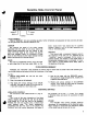
Minitmoog
Synthesizer
Model
300A
and
Satellite
Synthesizer
Model
5330,
manufactured
by
Moog
Music
Inc.,
2500
Walden
Avenue,
Buffalo,
New
York
14225.
This
manual
was
written
basically
for
the
Minitmoog
Synthesizer
which
includes
the
touch
sensor
board
4
and
oscillator
B
board
5
not
found
in
the
Satellite
Synthesizer.
Differences
in
operating
control
panel
markings
are
indicated
in
Section
5.
Any
major
differences
will
be
noted.
The
Minitmoog
and
Satellite
Synthesizers
are
monophonic
live
performance
synthesizers
intended
primarily
as
auxiliary
instruments
for
keyboardists
and
features
a
dozen
"QUICK-SET"
tabs
that
allow
for
instan
taneous
changes
among
various
voices
preset
with
in
the
instrument.
The
sound
producing
chain
of
the
Synthesizers
consists
of
an
"A"
oscillator
that
produces
both
sawtooth
and
rectangular
waveforms,
a
"B"
scillator
(Minitmoog
only)
that
produces
only
saw
tooth
waveforms,
a
band
pass
filter,
a
low
pass
filter
and
a
variable
gain
amplifier.
All
five
of
these
circuits
in
the
sound
producing
chain
are
voltage
controlled
and
the
remaining
circuitry
is
devoted
to
producing
appropriate
control
voltages.
The
keyboard
circuit
produces
one
pitch
control
voltage,
the
magnitude
of
which
depends
on
which
key
is
depressed.
In
addition,
the
keyboard
produces
a
trigger
voltage
whenever
one
or
more
of
the
keys
are
depressed.
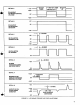
The
modulating
oscillator
produces
triangular
waveforms
for
modulating
the
oscillators
and
filters.
Two
contour
generators
produce
voltages
that
rise
and
fall
each
time
a
key
is
depressed.
One
contour
generator
sweeps
one
of
the
filters
while
the
other
sweeps
the
amplifier.
A
resistor
matrix
determines
the
nominal
values
of
the
voltage-controlled
parameters.
The
power
supply
delivers
±
18
volts
unregulated
and
±
9
volts
regulated.
Refer
to
page
52.
The
resistor
matrix
has
fifteen
input
rows
and
twelve
output
columns.
A
row
is
on
when
+9
volts
is
applied
to
it
and
off
when
it is
open
circuited.
The
two
upper
rows
are
connected
to
the
2
OCT
and
1
OCT
tab
switches,
respectively,
and
shorten
the
contour
times
and
raise
filter
frequencies
when
on.
The
remaining
rows
are
for
the
quick
set
voices
and
only
one
can
be
on
at
a
time.
The
column
outputs
are
applied
to
low
impedance
points
in
the
circuitry.
Of
the
twelve
matrix
output
columns,
eight
supply
control
currents
for
continuously
variable
parameters,
while
the
remaining
four
supply
switching
current
to
determine
circuit
states.
SECTION
2
CIRCUIT
DESCRIPTION
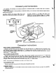
2.1
GENERAL
The
main
circuit
board
mounts
underneath
the
keyboard
and
contains
a
large
portion
of
the
Synthesizer
circuitry.
All
connections
to
this
board
are
made
through
Molex
connectors.
Looking
at
the
board
from
the
component
side
with
the
connectors
along
the
top
edge,
the
left
connector
is
designated
"A"
and
the
right
connector
is
designated
"B"
with
the
pins
numbered
from
1
to
24
starting
with
the
ief
t
pin
on
each
connector.
Block
diagrams,
schematic
diagrams
and
printed
circuit
board
diagrams
are
illustrated
in
Section
10
for
quick
reference.
2.2
POWER
SUPPLY
The
unregulated
portion
of
the
power
supply
is
located
on
power
supply
board
No.
2
and
is
completely
conventional.
The
nominal
total
load
supplied
from
each
of
the
unregulated
voltages
is
45
milliamperes.
The
positive
and
negative
voltage
regulator
circuits
for
the
power
supply
are
located
on
main
board
No.
1
.
The
positive
power
supply
voltage
regulator
consists
of
IC1
and
associated
components
and
its
circuitry
is
completely
conventional.
The
supply
delivers
55
or
60
milliamperes
before
voltage
15