
Service manual


developed
across
current
sense
resistor
R2
limits
the
current.
The
negative
power
supply
voltage
regulator
consists
of
IC2,
Ql
and
associated
components
and
adjusts
its
output
to
have
the
same
magnitude
as
the
regulated
+9
volt
output.
No
current
limiting,
other
than
that
supplied
by
R8,
is
provided.
2.3
KEYBOARD
CIRCUIT
The
keyboard
circuit
consists
of
IC3
thru
IC7,
IC9,
IC10
and
related
circuitry.
The
keyboard
contains
a
string
of
thirty-six
100-ohm
resistors
connected
between
pins
A5
and
A6.
The
current
through
the
resistor
string
is
regulated
by
IC7
so
that
the
drop
across
R79
and
R80
is
exactly
4.5
volts.
R79
is
set
so
that
the
voltage
at
pin
A6
is
exactly
-4.5
volts.This
sets
a
scale
factor
of
3
volts
per
octave
(250
mv
per
semitone).
2.3.1
TRIGGERING
(SINGLE)
The
voltage
at
the
keyboard
buss
is
applied
to
voltage
follower
IC4.
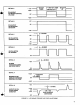
The
keyboard
buss
voltage
rises
to
approximately
7
volts
(detail
A,
Figure
2-1)
when
no
key
is
depressed
because
of
R53.
The
output
of
voltage
follower
IC4
is
applied
to
comparator
IC5
whose
output
swings
from
-16
to
+7
volts
whenever
the
input
goes
below
+4.8
volts
(detail
B).
Q5
and
Q6
comprise
a
monostable
multivibrator
producing
a
pulse
of
approximately
20
milliseconds
duration
(detail
C).
When
the
output
of
IC5
swings
positive,
a
positive
spike
is
applied
through
C7
and
D7
to
the
base
of
Q6,
initiating
a
20
millisecond
pulse.
R63,
R73
and
R72
are
proportioned
so
that
Q7
conducts
only
when
the
output
of
IC5
is
positive
and
the
output
of
the
monostable
multivibrator
(the
collector
of
Q5)
is
negative.
That
is,
Q7
begins
to
conduct
approxi
mately
20
milliseconds
after
a
key
is
depressed
and
stops
conducting
as
soon
as
all
keys
are
released.
When
Q7
conducts,
Q8
is
turned
on
and
the
voltage
at
its
collector
rises
from 0
to
+9
volts.
When
this
happens,
C13
discharges
through
R61
producing
a
ramp
voltage
at
the
base
of
Q4
that
decreases
from
+9
volts
to
-0.6
volt
in
approximately
20
milliseconds
(detail
E).
Emitter
follower
Q4
supplies
a
current
through
R62
and
Q3
to
turn
on
IC10.
IC10
and
Q51
with
associated
circuitry
comprise
a
sample
and
hold
circuit.
When
the
current
ramp
is
applied
to
pin 5 of
IC10,
the
voltage
at
the
source
of
Q51
rapidly
approaches
that
at
the
output
of
IC4.
As
soon
as
the
base
of
Q4
drops
below
0.8
volt,
the
bias
current
being
applied
to
IC10
through
Q3
drops
to
zero
and
the
voltage
at
the
source
of
Q51
remains
constant.
As
long
as
the
output
of
IC5
remains
positive
(that
is,
as
long
as
any
key
is
depressed),
a
very
small
bias
current
of
approximately
50
nanoamperes
flows
through
R59
allowing
IC10
to
supply
a
small
current
to
C5
keeping
its
voltage
constant.
As
soon
as
all
keys
are
released,
the
output
of
IC5
goes
negative
and
IC10
is
virtually
completely
shut
off.
Thus,
when
only
one
key
at
a
time
is
depressed,
the
voltage
at
the
source
of
Q51
begins
to
approach
the
new
key
voltage
approximately
20
milliseconds
after
the
key
is
depressed
and
this
voltage
is
equal
to
the
new
key
voltage
well
before the
ramp
current
turning
IC10
on
goes
to
zero.
As
long
as a
key
is
depressed,
the
correct
voltage
at
the source
of
Q51
is
maintained
by
the
small
trickle
current
going
through
R59.
When
the
key
is
released,
the
trigger
output
at
the
collector
of
Q8
drops
to
zero,
and
the
sample
and
hold
circuit
no
longer
samples
the
keyboard
voltage.
The
20
millisecond
delay
supplied
by
Q5
and
Q6
is
necessary
to
bypass
the
effect
of
contact
bounce
during
key
depression.
2.3.2
TRIGGERING
{MULTIPLE)
IC6
becomes
important
when
two
keys
are
de
pressed.
Any
abrupt
change
in
voltage
at
the
output
of
IC4
is
applied
through
R66
and
C10
to
the
input
of
IC6.
Cll
filters
out
spikes
less
than
1
millisecond
that
are
associated
with
contact
bounce
or
spurious
interference.
The
resulting
rounded
pulse
is
amplified
by
IC6
(detail
G,
Figure
2-1).
Whenever
the
keyboard
buss
voltage
increases,
the
output
of
IC6
goes
positive,
D9
conducts
and
fires
Q6
producing
a
20
millisecond
positive
going
pulse
at
the
collector
of
Q5.
While
this
20
millisecond
pulse
is
on,
the
trigger
voltage
at
the
collector
of
Q8
drops
to
zero.
Also,
the
collector
of
Q50
drops
to
zero.
This
causes
C13
to
recharge
to
+8.8
volts
at
the
leading
edge
of
the
20
millisecond
pulse
and
resets
the
contour
generators
which
are
described
later.
Thus,
when
a
key
is
held
down
and
a
higher
key
is
depressed,
the
keyboard
sample
and
hold
circuit
again
samples
and
the
trigger
is
reset
momentarily.
The
same
happens
when
a
higher
key
is
released
while
a
lower
key
is
being
held
16