
Service manual


down
since
Q6
is
fired
by
the
negative
going
output
pulse
of
IC5
coupled
via
C9,
R192,
R78
and
D10.
However,
if
the
higher
key
is
held
and
the
lower
key
is
depressed
or
released,
nothing
will
happen
since
the
keyboard
buss
voltage
remains
constant.
When
all
keys
are
released,
D9
conducts
and
a
20
millisecond
pulse
appears
at
the
collector
of
Q5.
However,
the
output
of
IC5
goes
negative,
so
that
when
the
collector
of
Q5
again
goes
negative,
Q8
is
not
reset.
2.3.3
KEYBOARD
CONTROL VOLTAGE
IC3
is
a
voltage
follower
whose
output
is
the
voltage
of
the
last
key
depressed.
Variable
resistor
R12
controls
the
glide
rate
and
is
connected
between
pins
A7
and
A24.
The
time
constant
of
this
resistor
and
C4
determines
the
glide
rate.
IC9
and
Q2
comprise
another
voltage
follower.
The
difference
between
this
voltage
follower
and
IC3
is
the
amount
of
input
current
required.
IC9
is
biased
at
a
low
current
level
so
that
input
current
does
not
result
in
a
pitch
error
when
the
glide
rate
potentiometer
is
at
its
maximum
resistance.
The
voltage
at
the
emitter
of
Q2
determines
the
pitch
of the
audio
oscillators
and
is
also
applied
to
the
filters
and
contour
generators
so
that
as
the
keyboard
voltage
goes
up, the
filter
frequency
also
goes
up
and
the
contour
time
constants
decrease.
2.4
OSCILLATOR
IC8
is
a
dc
summer
adding
pitch,
one-octave
transpose
voltage,
a
tuning
voltage
from
the
fine
tuning
potentiometer
on
the
rear
panel,
a
modulating
voltage
and
the
voltage
from
the
touch
sensor.
R14
is
a
temperature
compensating
feedback
resistor.
The
summation
constant
increases
with
a
temperature
coefficient
of
approximately
3400
parts
per
million.
The
relationship
between
R14
and
the
input
resistors
is
such
that
the
output
of
IC8
decreases
approximately
20
millivolts
for
each
octave
increase
in
frequency.
2.4.1
OSCILLATOR
A
The
oscillator
A
audio
sawtooth
waveform
is
generated
by
linearly
discharging
C38
through
one
of
the
transistors
in
IC11,
then
rapidly
recharging
it
through
Q45.
The
current
discharging
C38
is
determined
by
the
voltage
difference
between
pins
2
and
4
of
IC11.
The
ratio
of
currents
through
these
two
transistors
in
IC11
is
an
exponential
function
of
the
voltage
difference
between
their
bases.
The
current
fed
into
pin
1
of
IC11
is
kept
constant
by
IC21
which
maintains
the
voltage
at
pin
1
at
the reference
voltage
appearing
at
the
junction
of
R28
and
R29.
It
ac
complishes
this
via
current
feedback
to
pin
3
of
IC11.
The
overall
effect
is
that
C38
discharge
current
doubles
(increases
1
octave)
for
each
20
mv
increase
across
pins
2
and
4
of
IC11.
When
2
OCT
switch
is
up,
R30
conducts
and
Q49
is
saturated,
effectively
placing
the
series
combination
of
R20
and
R21
in
parallel
with
R19.
The
current
at
pin
1
of
IC11
is
then
de
termined
by
the current
flowing
through
parallel
resistors
R19
and
R20/R21.
When
2
OCT
switch
is
down,
R30
does
not
conduct,
Q49
is
open,
and
R20/
R21
are
out
of
the
circuit.
Thus
the
current
flowing
into
pin
1
of
IC11
is
25
percent
as
much
when
Q49
is
open
as
it
is
when
it
is
saturated
and,
for
the
same
voltage
difference
between
the
bases,
the
current
flowing
into
pin
5
is
also
25
percent
as
much.
The
lower
end
of
C38
is
applied
to
low-input-
bias-current
voltage
follower
IC12/Q46.
The
voltage
at
the
emitter
of
Q46
is
applied
to
Schmitt
trigger
Q43
and
Q44.
The
Schmitt
trigger
has
a
high
hysteresis
factor
and
when
the
voltage
descends
to
the
point
where
the
Schmitt
trigger
fires,
Q45
is
turned
on
and
C38
is
rapidly
recharged.
The
Schmitt
trigger
begins
to
shut
off
when
the
recharge
is
approximately
66
percent
complete.
Because
of
the
storage
time
of
Q44
and
Q45,
C38
is
fully
recharged
before
Q45
is
completely
off.
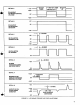
2.4.2
OSCILLATOR
A
WAVESHAPING
The
sawtooth
wave
developed
at
the
emitter
of
Q46
(Figure
2-2)
is
applied
through
R41
to
the
base
of
Q47
and
through
R43
to
the
collector
of
Q48.
The
width
of
the
rectangular
wave
that
appears
at
the
collector
of high
gain
amplifier
Q47
depends
on
the
bias
current
supplied
through
R45
from
the
output
FIGURE
2-2
EMITTER
OF
Q46
18