
Service manual


of
IC13.
The
control
current applied
to
the
input
of
IC13
from
the
resistor
matrix
determines
the
out
put
voltage
of
IC13.
When
the
control
current
is
zero,
Q47
remains
saturated
throughout
the
entire
sawtooth
cycle.
Q48
is
also
biased
by
IC13
(via
R118)
and
remains
shut
off
and
as
a
result,
the
output
voltage
is
the
undistorted
sawtooth.
As
the
control
current
increases,
the
voltage
at
the
output
of
IC13
goes
negative.
When
it is
approximately
-1
volt,
the
current
through
R118
is
sufficient
to
completely
saturate
Q48
and
effectively
short
out
the
sawtooth
waves.
When
it
is
approximately
-3
volts,
Q47
begins
to
conduct
on
part
of
the
sawtooth
cycle
and
a
narrow
rectangular
waveform
appears
at
its
collector.
When
the
voltage
at
the
output
of
IC13
is
approximately
-9
volts,
the
clipping
of
Q47
is
symmetrical
and
a
square
wave
appears
at
its
collector.
Thus,
the
waveform
at
the
junction
of
R119
and
R44
is
first
a
sawtooth
when
the
control
current
into
IC13
is
zero,
then
changes
to
a
narrow
rectangular,
then
to
a
broad
rectangular,
and
finally
to
a
square
wave
as
the
control
current
is
increased.
This
waveform
is
applied
to
the
band
pass
filter
via
an
attenuator
network
associated
with
oscillator
board
No.
5
(oscillator
B).
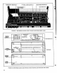
2.4.3
OSCILLATOR
B
(Minitmoog
Only)
The
circuitry
for
the
second
oscillator
is
located
on
oscillator
board
No.
5
and
consists
of a
current
source
network,
sawtooth
oscillator
and
a
mixing
network
for
combining
the
A
and
B
oscillator
tones.
The
sawtooth
waveform
is
produced
by
charging
C503
through
line
P
and
discharging
it
by
turning
on
Q501.
The
current
through
line
P
is
supplied
from
one
of
the
transistors
in
IC11
on
the
main
board.
This
particular
transistor
is
located
on
the
same
chip
with
the
current
source
transistor
for
oscillator
A
and
its
characteristics
are
very
close
to
those
of
the
oscillator
A
current
source.
As
a
result,
the
ratio
of
oscillator
A
to
oscillator
B
currents
will
be
fairly
constant
as
the
instrument's
pitch
is
varied.
Resistors
R501
thru
R510
supply
a
relatively
small
voltage
change
at
pin
M
to
vary
the
ratio
between
oscillator
currents
by
a
factor
of
4.
Oscillator
B
range
trimpot
R504
sets
the
center
value
of
oscillator
B
pitch.
When
pin
T
is
grounded
by
the
f
SYNC
tab
switch,
the
"B"
PITCH
control
moves
oscillator
B
pitch
up
and
down
an
octave
relative
to
oscillator
A.
When
pin
V
is
grounded
by
the
SYNC
tab
switch,
the
aB"
PITCH
control
sweeps
the
natural
frequency
of
oscillator
B
over
a
range
of
more
than
four
octaves.
In
this
case,
R505
shifts
the
pitch
of
oscillator
B
such
that
oscillators
A
and
B
are
approximately
in
unison
when
the
"B"
PITCH
control
is
fully
counterclockwise.
Note
that
the
"B"
PITCH
control
is
centertapped
with
a
center
deadband
to
allow
the
musician
to
quickly
and
precisely
set
oscillator
B
pitch
in
unison
with
oscillator
A.
Octave
trimpot
R510
is
set
so
that
the
pitch
of
oscillator
B
is
either
an
octave
above
or
below
that
of
oscillator
A
when
the
"B"
PITCH
control
is
at
either
end
of
its
rotation.
The
oscillator
circuitry
consists
of
IC501,
IC502
and
Q501
with
related
circuitry.
Q502
and
Q503
are
active
only
when
oscillator
B
is
synchron
ized
to
oscillator
A.
A
positive
going
pulse
is
produced
at
the
output
of
Schmitt
trigger
IC502
when
the
output
voltage
of
integrator
IC501
surpasses
the
threshold
voltage
at
the
junction
of
R514
and
R531.
Q501
is
turned
on
for
approximately
10
microseconds.
Trimpot
R511
increases
the
frequency
at
high charging
currents
and
is
used
as
a
high
end
tuning
adjustment.
The
sawtooth
waveform
appears
at
the
output
of
IC501.
Sync
pulses
from
oscillator
A
are
applied
at
pin
R
to
the
base
of
Q502.
When
+9
volts
are
connected
to
pin
Q
by
the
SYNC
tab
switch,
Q502
is
always
saturated.
When
pin
Q
is
grounded
by
the
SYNC
tab
switch,
the
sync
pulses
turn
Q502
off
and
Q503
on
once
for
every
cycle
of
oscillator
A.
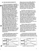
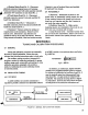
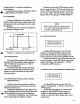
When
Q503
conducts,
the
threshold
of
IC502
drops
to
0 and
the
oscillator
B
waveform
starts
over
(Figure
2-3).
Resistors
R522
thru
R525
form
the
mixing
network.
The
A/B
MIX
control
on
the
front
panel
FIGURE
2-3
SYNCH
RON
IZA
TION
OF
OSCIL
LA
TOR
B
TO
OSCILLATOR
A
19