
Service manual


2.8
AMPLITUDE
CONTOUR
GENERATOR
Of
the
two
contour
generators,
the
amplitude
contour
generator
is
the
simplest,
so
it
will
be
described
first.
This
contour
generator
consists
of
Q34,
Q35,
Q36,
IC18,
transistor pairs
Q26/Q27
and
Q28/Q29,
Q30,
Q31,
Q32
and
associated
circuitry.
When
the
leading
edge
of
the
trigger
occurs,
Q35
partially
charges
C25
so
that
the
emitter
of
Q35
rises
to
approximately
3.5
volts.
If
Q36
is
saturated,
Q34
does
not
conduct
at
all.
Column
3
of the
resistor
matrix
determines
whether
or
not
Q36
is
turned
on.
If
Q34
is
not
turned
on,
C25
is
free
to
immediately
begin
linearly
discharging
through
Q26.
The
dis
charging
current
from
Q26
is
determined
by
the
voltage
control
developed
across
R189.
If
Q36
is
off,
Q34
holds
the
voltage
at
+3.5
volts
until
the
end
of
the
dc
trigger
occurs
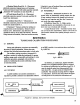
(detail
D,
Figure
2-1).
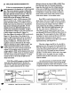
Thus,
the
voltage
at
the
emitter
of
Q35
is
as
shown
in
Figure
2-4.
The
rise
time
of the
voltage
at
the
emitter
of
Q35
is
determined
only
by
the
ability
of
Q35
to
discharge
C25.
Typically,
this
rise
time
is
less
than
1
millisecond.
The
decay
time
of
the
amplitude
contour
is
determined
by
the
voltage
difference
between
the
bases
of
Q26
and
Q27.
The
voltage
across
R189
results
from
the
amplitude
contour
decay
time
control
currents
coming
from
column
2
of
the
resistor
matrix,
the
keyboard
voltage
applied
to
R199
and
the
shaping
current
from
R169
and
R171.
R190
corrects
for
transistor
offsets
and
other
normal
component
variations.
A
voltage
increase
of
18.5
mv
at
the
base
of
Q26
cuts
the
decay
time
in
half.
IC18,
C35
and
Q32
comprise
a
voltage
follower
whose
slew
rate
is
proportional
to
the
bias
cur
rent
of
IC18.
This
bias
current
applied
from
the
collector
of
Q28
is
determined
by
the
voltage
difference
between
the
bases of
Q28
and
Q29.
Thus,
since
the
decay
time
of
an
envelope
is
generally
longer
than
the
attack
time,
the
voltage
appearing
at
the
source
of
Q32
has
an
attack
time
inversely
proportional
to
the
collector
current
of
Q26.
The
contributions to
attack
time
control
are
similar
to
those
of
decay
time
control.
The
quick-set
current
comes
from
column
1
of
the
resistor
matrix.
Since
Q26
is
a
nearly
ideal
current
source,
the
decay
slope
at
the
source
of
Q32
would
be
a
straight
line
if
not
for
the
action
of
Q30.
At
the
beginning
of
the
decay
slope,
the
voltage
at
the
base
of
Q30
is
more
positive
than
the
emitter,
and
Q30
does
not
conduct.
When
the
base
of
Q30
approaches
-0.6
volt
(i.e.,
when
source
of
Q32
is
equal
to
+1.8
volts),
Q30
acts
as
an
emitter
follower
and
the
cur
rent
through
R169
flows
to
R189
and
slows
down
the
decay
slope.
The
more
negative
the
base
of
Q30
goes,
the
higher
its
control
current
and
the
more
the
decay
slope
decreases.
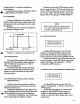
This
gives
the
decay
slope
an
extended
tail
and
therefore
sounds
like
a
more
natural
exponential
decay.
(See
Figure
2-5.)
When
the
voltage
at
pin
B21
is
+9
volts,
Q31
is
saturated
and
very
little
current
flows
through
R171.
When
the
voltage
at
pin
B21
is
zero,
Q31
is
open
and
current
flows
through
R170
and
R171
to
greatly
speed
up
the
decay
slope.
The
SUST
tab
switch
connects
pin
B21
to
+9
volts
when
it
is
down
and
to
the
trigger
line
when
it
is
up.
As
a
result,
the
tone
is
rapidly
squelched
when
the
SUST
tab
switch
is
up
and
the
keys
are
released.
As
noted
previously,
the
keyboard
pitch
voltage
controls
both
attack
and
decay
times
through
R199
and
R198,
respectively.
These
times
change
by
a
factor
of
approximately
2.5
over
the
complete
keyboard
range.
KEY
DOWN
035
EMITTER
(Q36OFF)
OV
-0.6
V
+3.5V—
Q35
EMITTER
(Q36
ON)
0V
-0.6V
=f
r
KEY
UP
FIGURE
2-4
EMITTER
VOL
TAGE
OF
Q35
+3.5V
Q32
SOURCE
(Q36OFF)
0V
-0.6V
+3.5V-
032
SOURCE
(Q36
ON)
OV
-0.6
V
h-KEYDOWNh—
KEY
UP
FIGURE
25
SOURCE
VOL
TAGE
OF
Q32
21