
Service manual


(as
a
result
of
pressing
down
harder
upon
a
key),
the
voltage
at
the
junction
of
R404
and
R406
begins
to
-i$e.
Thus
IC402,
Q402,
Q403
and
related
circuitry
yrnPa
dc
restorer
that
keeps
the
voltage
at
the
junction
of
R404
and
R406
at
zero
until
a
key
is
depressed
and
returns
it
to
zero
when
a
key
is
released.
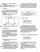
2.11.4
AMPLIFIER
The
voltage
at
the
junction
of
R404
and
R406
is
applied
to
open
loop
amplifier
IC403.
The
value
of
R408
is
set
so
that
the
input
of
IC403
begins
to
saturate
when
the
touch
control
output
rises
to
ap
proximately
50
percent
of
its
maximum
value
and
saturates
more
and
more
as
the
touch
sensor
element
is
depressed
further*
This
allows
the
touch
sensor
to
be
more
sensitive
at
the
beginning
of
its
travel
and
to
become
increasingly
less
sensitive
as
a
key
is
depressed
with
more
force.
The
touch
control
output
at
pin
G
rises
from
0
to
approximately
+6
volts
and
sweeps
the
filters,
both
oscillators
or
just
the
second,
oscillator
depending
on
how
the
front
panel
touch
sensor
switches
are
set.
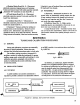
2.11.5
MODULATION
AMOUNT
The
touch
control
output
from
pin
6
of
IC403
is
also
applied
through
R411
and
Q404
to
control the
gain
of
IC404.
The
triangular
modulation
wave
is
applied
at
pin
H
from
the
output
of IC2.
The
modu
lating signal
of
varying
amplitude
at
pin
J
is
available
for
modulation
when
the
TOUCH
CONTROLS
MOD
tab
switch
is
depressed.
It
should
be
noted
that
the
ratio
between
R412
and
R413
is
set
so
that
C409
rounds
off
the
triangular
wave
to
yield a
desirable
sinusodial
wave
effect.
SECTION
3
DISASSEMBLY,
VISUAL
INSPECTION
AND
REASSEMBLY
3.1
DISASSEMBLY
3.2
VISUAL
INSPECTION
Disassembly
and
inspection
are
essentially
the
same
for
both
Synthesizers
except
where
the
Touch
Sensor
Board
4
and
the
Oscillator
Board
5
are
mentioned.
These
boards
are
used
only
on
the
Minitmoog.
a)
Disconnect
power
cord
connector
and
all
other
rear
panel
connections.
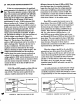
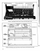
b)
Stand
instrument
on
one
ei.d
and
remove
three
screws
securing
large
bottom
cover
(Figure
3-1)
to
instrument
using
a
medium
sized
Phillips
head
screwdriver
and
remove
cover.
NOTE
All
internal
alignment
and
adjustment
controls
are
now
accessible.
c)
If
necessary,
the
narrow
bottom
cover
may
be
removed
by
taking
out
an
additional
10
screws.
a)
Inspect
instrument
for
broken
wires,
loose
printed
circuit
boards
or
electrical
connectors,
cable
harness
wires
pushed
into
keyswitches
and
rotary
pots
with
terminals
shorted
to
chassis.
b)
Check
for
frayed
conductive
nylon
on
touch
sensor
assembly
shorting
to
keyboard
switch
assembly.
3.3
PRINTED
CIRCUIT
BOARD
REMOVAL
a)
Main
Board
No.
1
-
Disconnect
5
electrical
connectors,
depress
levers
on
6
fastening
devices
and
remove
board
from
bottom
cover.
(See
Figure
3-1.)
b)
Power
Supply
Board
No.
2
-
Remove
7
slide
knobs,
narrow
bottom
cover,
2
electrical
connectors,
2
screws
and
1
foot
and
carefully
lift
power
supply
from
instrument.
WARNING
Removing
narrow
bottom
cover
exposes
live
terminals
of
the
ac
POWER
tab
switch.
Use
extreme
care
when
power
cord
is
connected
to
primary
power.
WARNING
Removing
narrow
bottom
cover
exposes
live
terminals
of
the
ac
POWER
tab
switch.
Use
extreme
care
when
power
cord
is
connected
to
primary
power.
23