
Service manual


c)
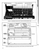
Resistor
Matrix
Board
No.
3
—
Disconnect
electrical
connector,
depress
levers
on
4
fastening
devices
and
remove
board
with
cable
assembly
attached.
Jisconnect
"D"
connector
on
main
board
No.
1.
d)
Touch
Sensor
Board
No. 4
—
Disconnect
electrical
connector,
remove
2
nuts
and
carefully
lift
board
from
instrument.
e)
Oscillator
Board
No.
5
—
Disconnect
2
electrical
connectors,
remove
2
nuts
and
carefully
lift
board
from
main
board
No.
1.
f)
Keyboard
—
Remove
cabinet
by
taking
out
4
small
screws
on
the
end
pieces.
Remove
narrow
bottom
cover.
Disconnect
1
snap
fastener
and
unsolder
3
wires
(1
at
top
and
2
at
bottom).
Remove
2
large
screws
and
washers,
2
hex
head
screws
securing
L-bracket
to
rear
of
keyboard
frame
and
carefully
lift
keyboard
from
chassis.
3.4
REASSEMBLY
a)
Keyboard
-
Reassemble
keyboard
in
the
reverse
order
of
disassembly
making
certain
that
the
2
large
washers
between
the
chassis
and
keyboard
frame
are
not
forgotten
and
that
the
2
screws
do
not
touch
the sensor
assembly.
b)
Oscillator
Board
No.
5
-
Make
certain
insulating
spacers
are
reinstalled
so
that
nuts
do
not
short
out
top
or
bottom
side
of
board.
c)
Large
Bottom
Cover
-
Ascertain
harness
wires
are
not
forced
into
keyswitches.
Assure
cover
does
not
pinch
matrix
harness
wires
passing
through
cutout
in
chassis.
SECTION
4
TUNING
AND
CALIBRATION
PROCEDURES
4.1
GENERAL
Tuning
and
calibration
procedures
are
essentially
the
same
for
both
Synthesizers.
Unless otherwise
indicated
the
following
instructions
apply
to
both
units.
The
oscillator
tuning
procedure,
paragraph
4.2,
provides
a
method
of tuning
the
instrument
for
proper
oscillator
range,
scale,
octave
shift
and
tracking.
A
voice
calibration
procedure,
paragraph
4.3,
provides
a
method
of
calibrating
the
sound
modifying
circuits
to
voice
the
presets.
4.2
OSCILLATOR
TUNING
4.2.1
TEST
SETUP
A
stable
oscillator
(or
another
synthesizer)
is
required
to
provide
a
reference
tone
(hereafter
referred
to
as
REF)
tunable
a
few
semitones
above
and
below
Bb4
(466
Hz).
REFERENCE=
=
466Hz
In
addition,
an
oscilloscope,
digital
voltmeter
(DVM)
and
an
amplifier/speaker
system
is
required
for
tuning
and
calibration
and
oscillator
board
No.
5
must
be
carefully
raised
(not
disconnected)
from
main
board
No.
1
to
gain
access
to
trimpots
R16
and
R190.
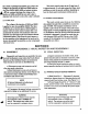
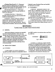
The
minimal
test
setup
shown
in
Figure
4-1
will
suffice.
However
the
setup
shown
in
Figure
4-2
will
prove
to
be
much
more
convenient
and
FIGURE
4
1
MINIMAL
TEST
SETUP
FOR
TUNING
25