
Service manual

c)
Repeat
paragraphs
4.2.12
and
4.2.13
several
times
as
scale
and
high
end
adjustments
interact.
4.2.14
OSCILLATOR
B
OCTAVE
TRANSPOSITION
(Minitmoog
Only)
1
OCT
tab
switch
down
2
OCT
tab
switch
up
"B"
PITCH
control
vertical
(in
deadband)
a)
Zero
beat
oscillator
B
with
oscillator
A
using
range
trimpot
R504,
Figure
4-5
(oscillators
A
and
B
in
unison).
b)Set
"B"
PITCH
control
fully
clockwise
to
10
and
zero
beat
oscillator
B
with
oscillator
A
using
octave
trimpot
R510,
Figure
4-5
(oscillator
B
one
octave
above
oscillator
A).
NOTE
Allow
a
small
adjustment
latitude
by
tuning
oscillator
B
slightly
sharp
in
step
b
(approx
imately
2
Hz
beat
rate).
Thus
oscillator
B
will
be
in
tune
with
oscillator
A
slightly
before
the
control
reaches
full
rotation.
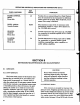
4.3
VOICE
CALIBRATION
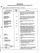
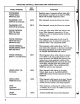
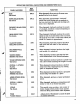
4.3.1
PREPARATION
Set
the
following
controls
to
their
initial
position
as
follows:
Satellite
panel
marking
differences
are
in
parentheses.
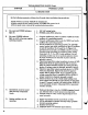
4.3.2
SQUARE
WAVE
DUTY
CYCLE
a)
Observe
waveform
at
junction
of
R44
and
R119
(Figure
4-3).
b)
Depress
CLARINET
(REED
HOLLOW,
Satellite)
tab
switch
and
adjust
square
wave
adjust
trimpot
R47
for
a
symmetrical
square
wave
as
shown
in
Figure
4-6.
EXACTLY
50%
DUTY
CYCLE
FIGURE
46
SQUARE
WAVE
AT
JUNCTION
OF
R44ANDR119
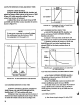
4.3.3
BAND
PASS
FILTER
RESONANCE
(Q)
AND
CENTER
FREQUENCY
(Fc)
a)
Observe
waveform
at
source of
Q41
(Figure
4-3)
with
CLARINET
(REED
HOLLOW,
Satellite)
tab
switch
still
depressed.
b)
Depress
1
OCT
tab
switch
and
C
key one
octave
up
from
bottom
of
keyboard
and
adjust
band
width
and
center
frequency
trimpots
R130
and
R132
to
obtain
waveform
shown
in
Figure
4-7.
4
UNITS
1UNIT
700
USEC
(Fc:
R132)
4:
1
RATIO
(Q:
R130)
V^>»-^
FIGURE
4-7
BAND
PASS
FIL
TER
Q
AND
Fc
AT
Q41
SOURCE
4.3.4
LOW
PASS
FILTER
CUTOFF
FREQUENCY
(FL)
a)
Raise
all
tab
switches
and
depress
highest
key
on
keyboard.
b)
Set
VOLUME
slide
control
all
the
way
up
and
adjust
low
pass
cutoff
trimpot
R139
(Figure
4-3)
until
the
waveform
at
output
pin
6
of
IC22
(top
of
R162)
is
two
volts
peak-to-peak.
29