
Service manual

4.3.5
FILTER
CONTOUR
ATTACK
AND
DECAY
TIMES
a)
Depress
1OCT
tab
switch.
b)
Depress
MUTE
(BRASS
MUTE,
Satellite)
tab
switch
and
observe
filter
contour
at
the
source of
Q20
(Figure
4-3)
while
repeatedly
striking
C
key one
octave
from
bottom
of
keyboard.
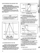
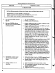
c)
Adjust
filter
decay
and
attack
trimpots
R98
and
R105
until
the
filter
contour
matches
the
pattern
shown
in
Figure
4-8.
NOTE
It
may
prove
convenient
to
externally
trigger
the
oscilloscope
from
the
bottom
of
R64
for
paragraphs
4.3.5
through
4.3.7.
~
+1.7V-
ov-
-0.5V-
R105
ATTACK
R98
DECAY
200
MSEC
'
200
MSEC
FIGURE
4-8
FIL
TER
CONTOUR
A
T
Q20
SOURCE
4.3.6
LOUDNESS
CONTOUR
ATTACK
TIME
a)
Observe
waveform
at
junction
of
R165
and
R166
(Figure
4-3)
with
MUTE
(BRASS
MUTE,
Satellite)
and
1
OCT
tab
switches
still
down.
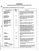
b)
Depress
C
key
one
octave
up
from
bottom
of
keyboard
and
adjust
amplitude
attack
trimpot
R174
to
match
the
attack
contour
shown
in
Figure
4-9.
+3.7V.
KEY
DOWN-*
0V-
^60-70.
MSEC
-20
MSEC
FIGURE
4-9
LOUDNESS
ATTACK
A
T
JUNCTION
OF
R165
AND
R166
4.3.7
LOUDNESS
CONTOUR
DECAY
TIME
a)
Lift
MUTE
(BRASS
MUTE,
Satellite)
tab
switch
and
depress
PIANO
(STRING
STRIKE,
Satellite)
tab
switch.
b)
Assure
1
OCT
tab
switch
is still
down
and
depress
C
key
one
octave
up
from
bottom
of
keyboard.
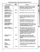
c)
Observe
waveform
at
junction of
R165
and
R166
(Figure
4-3)
and
adjust
amplitude
decay
trimpot
R190
for
the
decay
contour
shown
in
Figure
4-10.
J
FIGURE
4-JO
LOUDNESS
DECA
Y
ATJUNCTION
OF
R165
AND
R166
4.3.8
VOLTAGE
CONTROLLED
AMPLIFIER
BALANCE
a)
Lift
PIANO
(STRING
STRIKE,
Satellite)
tab
switch
and
short
junction
of
R149
and
C30
(Figure
4-3)
to
ground.
b)
Set
VOLUME
slide
control
at
maximum
and
connect
oscilloscope
probe
to
top
of
R162.
c)
Hit
and
release
a
key and
adjust
VCA
balance
trimpot
R160
until
a
minimum
click
or
thump
is
heard
and
step
waveform
at
top
of
R162
does
not
exceed
lOmv.
4.3.9
VIBRATO
DEPTH
a)
Set
vibrato
depth
trimpot
Rl
fully
CCW.
I
30