
Service manual
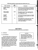

SECTION
5
OPERATING
CONTROLS,
INDICATORS
AND
CONNECTORS
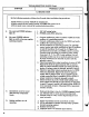
Satellite
Synthesizer
panel
marking
differences
are
shown
in
parentheses.
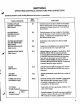
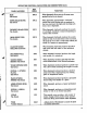
PANEL
MARKING
REF
DESIG
FUNCTION
FILTER
ATTACK
(FILTER
CONTOUR)
Slide
Control
FILTER
DECAY
(FILTER
COLOR)
Slide
Control
FILTER
BRIGHTNESS
(FILTER
EMPHASIS)
Slide
Control
MODULATION
RATE
Slide
Control
MODULATION
DEPTH
Slide
Control
R7
R8
R9
RIO
Rll
GLIDE
Slide
Control
VOLUME
Slide
Control
POWER
Tab
Switch
and
Indicator
Light
R12
R13
SW21
"B"
PITCH
\
Variable
Resistor/
A/BMIX
Variable
Resistor/
WMinitmoog
(
Only)
Controls
amount
of
time
it
takes
for
the
bright
ness
to
reach
a
peak;
0
is
the
normal
setting,
-4
indicates
the
longest
attack
and
+4
the
shortest
attack
times.
Controls
amount
of
time
it
takes
for
the
bright
ness
to
die
away
on
most
voices;
0
is
the
normal
setting,
-4
indicates
the
longest
decay
and
+4
the
shortest
decay
times.
Determines
voice
clarity
from
dull
to
bright
sounds.
Varies
rate
of
modulation
from
approximately
one
per
second
at
0
to
a
buzz
rate
at
10.
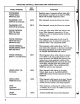
Adjusts degree
or
intensity
of
modulation.
With
MODULATION
VIB
tab
switch
depressed,
increasing
MODULATION
DEPTH
corresponds
to
periodic
frequency
deviation
that
increases
from
zero
to
more
than
one
octave.
With
MODULATION
TREM
tab
switch
depressed,
increasing
MODULATION
DEPTH
corresponds
to
greater
periodic
timbre
variation.
Adjusts
keyboard
glide
time
from
note
to
note
from
0
to
4
seconds
when
GLIDE
tab
switch
is
depressed.
Adjusts
Synthesizer
output
level
over
a
range
of
30dB.
Controls
primary
power
supplied
to
instrument.
Red
indicator
light
indicates
when
POWER
tab
switch
is
depressed
and
primary
power
is
supplied
to
the
instrument.
Varies
pitch
of
B
tone
producing
oscillator
over
a
two
octave
range.
Controls
mixing
of
A
and
B
tone
source
oscillator
outputs.
A
only
or
B
only
occur
at
the
CCW
and
CW
extremes
of
rotation,
respectively.
31