
Service manual
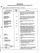
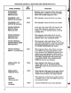
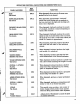

TROUBLESHOOTING
GUIDE
(Cont.)
SYMPTOM
PROBABLE
CAUSE
7.2
SOUND
CHAIN
Set the
following
controls
as
follows
for
all
sound
chain
troubleshooting
procedures.
All
tab
switches
up
except
VIOLIN
tab
switch
down.
All
slide
controls
at
zero
position
except
VOLUME
slide
control
at
10.
All
front
panel
rotary
controls
full
counterclockwise
position.
A.
No
sound
and
POWER
indicator
light
off.
B.
No
sound,
POWER
indicator
light
on
and
9
volt
power
supplies
operating
properly.
C.
Intermittent
sound
or
sound
dies
when
key
is
depressed
firmly.
D.
Neither
oscillator
A
or
B
operating.
1.
115
VAC
wiring
faulty.
2.
POWER
switch
SW21
defective.
1.
Connect
oscilloscope
probe
to
emitter
of
Q46
and
verify
oscillator
A
is
operating
properly.
2.
Connect
oscilloscope
probe
to
pin
6
of
IC501
and
verify
oscillator
B
is
operating
properly.
3.
If
both
oscillators
are
operating
properly,
set
A/B
MIX
control
vertical
and
check
waveforms
on
pins
Z
(oscillator
A)
and
ZZ
(oscillator
B)
of
board
No.
5
(Figure
4-5).
Levels
should
cross
fade
as
A/B
MIX
control
is
rotated.
Trouble
would
most
likely
be
caused
by
faulty
wiring
from
pins
S,
X,
Y,
Z
or
ZZ.
If
only
oscillator
A
is
not
operating,
trouble
may
be
in
waveform
selector
circuit.
If
proper
waveforms
are
observed
on
pins
Z
and
ZZ,
proceed
to
step
4.
4.
Check
band
pass
filter
output
waveform
at
source
of
Q41.
Signal
level
should
be
approximately
300
mv
peak-to-
peak.
No
output
indicates
trouble
is
in
band
pass
filter
section.
If
proper
output
is
observed,
proceed
to step
5.
5.
Check
low
pass
filter
output
waveform
at
pin
1
of
IC20
with
a
key
depressed.
Signal
level
should
be
approxi
mately
400
mv
peak-to-peak.
If
not,
trouble
is
in
the
voltage
controlled
filter
or
amplifier
(IC19
or
IC20).
If
proper
waveform
is
observed,
proceed
to
step
6.
6.
Check
waveform
at
pin
6
of
IC22
while
holding
a
key
down.
Signal
level
should
be
approximately
3
volts
peak-
to-peak.
If
normal,
trouble
is
in
output
wiring,
R236,
J3,
J4
or
associated
circuitry.
Otherwise
IC22
or
associated
circuitry
is
faulty.
1.
Keyboard
shorting to
top
of
a
CA3080
integrated
circuit
can.
Shorten
leads
or
touch
sensor
mounting
studs.
2.
Harness
wiring
or
rotary
control
lug
shorting
to
front
panel
extrusion.
1.
Faulty
exponential
current
source
IC11
or
IC21.
2.
IC8
or
associated
dc
summer
circuitry
faulty
(possible
shorted
summing
resistor).
3.
Resistor
R14
broken.
4.
Improper
input
to
dc
summer
input
resistors.
38