Section 3 - Wiring and Installation DS2100 Digital Controller PRELIMINARY INSTALLATION & USER' S MANUAL C7750-001 Rev.
SECTION 3: WIRING AND INSTALLATION SECTION 3: DS2100 User's Manual (Preliminary) WIRING AND INSTALLATION PAGE 3-1
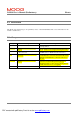
Errata Sheet DS2100 User's Manual (Preliminary) ERRATA E: PAGE 1 PDF created with pdfFactory Pro trial version www.pdffactory.
DS2100 User's Manual (Preliminary) Errata E.1 Introduction This Errata sheet details changes to the preliminary release of the DS2100 Manual. The corrected information for the manual is detailed below. E.2 Changes Page 1-5 3-54, 3-74 2-7 3-64 3-54, 3-74 Description Update to DS2100 Boxcar Error in Encoder connector wiring diagram Line fuses specified in manual for Size C drives incorrect. Figure 3.46 Incorrect.
DS2100 User's Manual (Preliminary) 3.11.5 Errata Motor Encoder Connection The DS2100 encoder input supports a variety of encoders. These include Analogue, SSI, Hiperface and Endat. The connections to the drive for each of these encoder types are given in Table 3.25. Encoder Connector - Figure 3.38 Motor Encoder Connector Location Fixed connector: 15 pin, female Sub-D connector Mating connector, 15pin male Sub-D Wiring: cable. 28-18AWG (0.14-0.82mm2) Encoder Type Pos Analogue SSI Hiperface J4.1 J4.
Errata Sheet DS2100 User's Manual (Preliminary) 3.14.5.7 Encoder - Fixed connector: 15 pin, female Sub-D connector - Mating connector, 15pin male Sub-D - Wiring: cable. 28-18AWG (0.14-0.82mm2) 15-Pin Sub-D Connector Plug (male) on cable DS2100 Cable End J4 Encoder Type Hiperface Pos Analogue SSI J4.1 J4.2 J4.3 J4.4 J4.5 J4.6 J4.7 J4.8 J4.9 J4.10 J4.11 Shield - Sine - Cosine Gnd Supply - Channel Z (Zero) NTC/PTC + Sine + Cosine +5 V .. +12V Supply (150 mA max.
Errata Sheet DS2100 User's Manual (Preliminary) 3.13.1 RS232 Serial Communications Interface The pin assignment enables use of a 9-pin Sub-D cable with all signals connected straight through. Serial Communications Connector (RS232) Figure 3.45 RS232 Connector Location - Fixed connector: 9 pin, female Sub-D connector Mating connector, 9 pin male Sub-D Wiring: cable. 28-18AWG (0.14-0.82mm2) Pos. J1.1 J1.2 J1.3 J1.4 J1.5 J1.6 J1.7 J1.8 J1.
DS2100 User's Manual (Preliminary) SECTION 3: WIRING AND INSTALLATION TABLE OF CONTENTS SECTION 3: WIRING AND INSTALLATION ........................................................................................................ 3-1 3.1 System Components ......................................................................................................................................... 3-4 3.1.1 A.C. Mains Power Interface..................................................................................
SECTION 3: WIRING AND INSTALLATION 3.14.3 3.14.4 3.14.5 DS2100 User's Manual (Preliminary) C Size Power Stage ................................................................................................................................ 3-69 D Size Power Stage ................................................................................................................................ 3-70 Control Card ...................................................................................................
DS2100 User's Manual (Preliminary) SECTION 3: WIRING AND INSTALLATION This section covers the installation, wiring and cabling of the Moog DS2100 Servo-drive series. A pictorial diagram of a single-axis system, with typical components included, is shown in Figure 3.1. Users are directed to read Section 2, Safety Instructions, before proceeding with wiring and installation.
SECTION 3: WIRING AND INSTALLATION DS2100 User's Manual (Preliminary) 3.1.2 A.C. Input Line Protection Details of the recommended Line fuses are given in Section 2 of this manual. Alternatively an AC mains Circuit Breaker (Instantaneous Trip Type) can be used as a protective device provide its ratings are equivalent to the recommended fuses.
DS2100 User's Manual (Preliminary) SECTION 3: WIRING AND INSTALLATION Figure 3.
SECTION 3: WIRING AND INSTALLATION DS2100 User's Manual (Preliminary) 3.1.4 Serial Set-up Terminal (User-Supplied) An RS-232 interface should be established for individual servo-drive communications, using a PC. The PC can run Moog's WinDrive Windows-based user-interface program.
DS2100 User's Manual (Preliminary) SECTION 3: WIRING AND INSTALLATION 3.1.6 Brushless Servo motors The DS2100 series Servo-drive is compatible with Moog brushless servomotors. Normal connection to the motor requires two cables - a power and a signal cable. The power cable provides three-phase stator power, protective earth and brake connections. The signal cable carries position transducer feedback signals and motor temperature detection connections. 3.1.6.
SECTION 3: WIRING AND INSTALLATION DS2100 User's Manual (Preliminary) 3.2 Equipment Mounting This section details the mechanical dimensions of the DS2100 chassis, as well as required clearances for cabling etc. The DS2100 is designed to be panel or cabinet mounted. The DS2100 must be mounted in a vertical orientation. The DS2100 must be panel mounted within an enclosure or cabinet that provides a degree of ingress protection against liquids and objects of at least IP54.
DS2100 User's Manual (Preliminary) SECTION 3: WIRING AND INSTALLATION Figure 3.2 Typical DS2100 Cable Bend Radius Requirements The DS2100 must be permanently and reliably connected to Earth and all conductive parts in the IP54 rated enclosure or cabinet must be permanently connected to Earth. The impedance between the earth terminal and any accessible part of the enclosure or cabinet should be less than or equal to 0.1 W.
SECTION 3: WIRING AND INSTALLATION DS2100 User's Manual (Preliminary) Figure 3.
DS2100 User's Manual (Preliminary) SECTION 3: WIRING AND INSTALLATION Figure 3.
SECTION 3: WIRING AND INSTALLATION DS2100 User's Manual (Preliminary) Figure 3.
DS2100 User's Manual (Preliminary) SECTION 3: WIRING AND INSTALLATION Figure 3.
SECTION 3: WIRING AND INSTALLATION DS2100 User's Manual (Preliminary) Figure 3.
DS2100 User's Manual (Preliminary) SECTION 3: WIRING AND INSTALLATION 3.2.1 CE Items for Mechanical Installation Additional electromagnetic compatibility (EMC) measures must be installed on equipment associated with the DS2100 Servo-drive.
SECTION 3: WIRING AND INSTALLATION DS2100 User's Manual (Preliminary) 3.3 Power Dissipation To calculate cabinet cooling requirements, Table 3.2 provides approximate equipment power dissipation values. If the application employs regeneration, be sure to add the regen resistor power dissipation to the numbers quoted in Table 3.2 below, (use the continuous wattage rating of the regen resistor if the actual application regen dissipation is unknown).
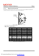
DS2100 User's Manual (Preliminary) SECTION 3: WIRING AND INSTALLATION 3.4 DS2100 Connector Terminals Figure 3.8 to Figure 3.12 below detail the connectors on the DS2100 (all sizes). Serial Communications Connector (RS232) Motor Resolver Connector Digital Input Connector Digital Output Connector Motor Encoder Connector Drive Ready Relay Connector Motor Brake Connector CAN Field Bus Interface Figure 3.
SECTION 3: WIRING AND INSTALLATION DS2100 User's Manual (Preliminary) Figure 3.9 DS2100 Size mA Power Connector Terminals Figure 3.
DS2100 User's Manual (Preliminary) SECTION 3: WIRING AND INSTALLATION J6 J9 J8 J7 Figure 3.
SECTION 3: WIRING AND INSTALLATION DS2100 User's Manual (Preliminary) Figure 3.
DS2100 User's Manual (Preliminary) SECTION 3: WIRING AND INSTALLATION 3.5 General System Wiring Guidelines The following is a general reminder of the cable requirements for the DS2100 Series Servo-drives and related equipment. NOTE - Cabling and component wiring is critical in obtaining successful operation of the system. Pay close attention to specified wiring practice, cabling information, earthing and shielding requirements.
SECTION 3: WIRING AND INSTALLATION DS2100 User's Manual (Preliminary) CAUTION - All external electrical wiring connected to this equipment must be color coded in accordance with European Standard EN 60204-1 requirements.. Required for CE-Compliance CAUTION - Additional electromagnetic compatibility (EMC) measures which must be installed on equipment cables associated with the DS2100 Servo-drive are given in Section 2 of this User’s Guide.
DS2100 User's Manual (Preliminary) SECTION 3: WIRING AND INSTALLATION 3.5.2 Wiring notes for J6, J7, J9 connectors (Size C) The connectors used on the DS2100 Size C are are formed using crimp terminals. The appropriate crimps (Molex type 42815-0031) are supplied together the floating connectors for J6, J7, and J9. These crimps are sized for a 8 AWG (8.4 mm2) cable with a 10 mm wire stripping. It is recommended to use the appropriate Molex crimping tool (63814-0000, or 63811-1500, or equivalent).
SECTION 3: WIRING AND INSTALLATION 3.6 DS2100 User's Manual (Preliminary) Sequence of Component Wiring Recommendations The following sequence for wiring is a recommendation. Individual wiring steps are denoted by a box character, which can be used as an installation check off list. The terminal block layout on all power supplies and servo-drives has been designed to isolate low voltage from high voltage circuits. Cabinet conduits should be arranged to maintain this physical separation.
DS2100 User's Manual (Preliminary) SECTION 3: WIRING AND INSTALLATION 3.7 Three-Phase A.C. Mains Power Source Configuration The DS2100 may be supplied from a three-phase a.c. mains input. In this case the following user supplied options are required:1. Three-Phase Mains Fusing 2. Mains Line Filter 3. 24Vd.c. Power Source & Fuse 4. 24V d.c. EMC Filter Note that for DS2100 sizes A,B,C & D, if the a.c.
DS2100 User's Manual (Preliminary) SECTION 3: WIRING AND INSTALLATION AC Mains Supply 24V Supply Mounting Backplane Line Fuses Contactor 24V Supply Fuse 24V EMC Filter Line Filter 3-Phase Supply & Protective Earth System Controller DC Bus Sharing DS2100 DS2100 Notes 1) Keep all cables as short as possible 2) Use Shielded\armourd cables 3) Ensure good HF bond to earth or chassis Regeneration Resistor Motor Position Feedback Cable Motor Position Feedback Cable Figure 3.
DS2100 User's Manual (Preliminary) SECTION 3: WIRING AND INSTALLATION 3.7.1 AC Mains Power Source Connection Size mA 3.7.1.1 a.c. Mains L1 EMC Filter, Fuses etc. L2 L3 Protective Earth See Section 2 Installation 4 5 L1 L2 6 L3 Connector J6 PE Stud 4 5 6 L1 L2 L3 PE Stud Connector J6 mA mA Figure 3.15 mA AC Mains Input Connection - Fixed connector: 12 pins, male connector Mating connector, 12 pins, female, supplied with the drive. Phoenix Combicon (Part # GMSTB 2.5/12-ST-7.
DS2100 User's Manual (Preliminary) SECTION 3: WIRING AND INSTALLATION 3.7.1.2 Size A & B a.c. Mains L1 EMC Filter, Fuses etc. L2 L3 Protective Earth See Section 2 Installation 4 5 6 L1 L2 L3 PE Stud Connector J6 A&B Figure 3.16 A & B AC Mains Input Connection - Fixed connector: 10 pins, male connector Mating connector, 10 pins, female, supplied with the drive. Phoenix Contact (Part # PC4 HV/10-ST-7.62) A size wiring: cable 14AWG (2.1 mm2). Wire stripping: 7 mm B size wiring: cable 12AWG (3.
DS2100 User's Manual (Preliminary) 3.7.1.3 SECTION 3: WIRING AND INSTALLATION Size C a.c. Mains L1 L2 L3 Protective Earth EMC Filter, Fuses etc. See Section 2 Installation 3 2 1 L1 L2 L3 PE Stud Connector J6 C Figure 3.17 Size C AC Mains Input Connection - Fixed connector: 5 pins, male connector Mating connector, 5 pins, female, crimped supplied with the drive. (Molex 42816-0512) C size wiring: cable 8 AWG (8.4 mm2). PE Stud wiring: cable 6 AWG (13mm2) Pos. J6.3 J6.2 J6.
DS2100 User's Manual (Preliminary) SECTION 3: WIRING AND INSTALLATION 3.7.1.4 Size D a.c. Mains L1 EMC Filter, Fuses etc. L2 L3 Protective Earth See Section 2 Installation 4 5 6 L1 L2 L3 3 PE Connector J9 D Figure 3.
DS2100 User's Manual (Preliminary) SECTION 3: WIRING AND INSTALLATION 3.8 24V Backup Connection The DS2100 is equipped with a 24V logic supply backup. This backup supply provides logic power to the drive when AC mains power is removed. For the mA size, this backup is mandatory for drive operation. 3.8.1 Size mA 24V Input Connection 24V Auxiliary Supply Fuse Fairrite Clamp Core p/n # 00443164151 (4-Turns of Supply cable) +24V GND (0V) 11 12 11 12 Connector J6 Connector J6 mDS mDS Figure 3.
DS2100 User's Manual (Preliminary) SECTION 3: WIRING AND INSTALLATION 3.8.2 Size A,B,C & D 24V Input Connection 24V Auxiliary Supply Fuse +24V GND (0V) Schaffner FN2070-3-06 Filter 1 2 Connector J8 A,B,C & D Figure 3.20 Size A,B, C & D 24V DC Input Connection - Fixed connector: 2 pins, male connector Mating connector, 2 pins, female, supplied with the drive. Wago (Part # 231-102/026-000) A,B,C & D size wiring: cable 14 AWG (2.1 mm2). Stripping Length 8mm Pos. J8.1 J8.
DS2100 User's Manual (Preliminary) SECTION 3: WIRING AND INSTALLATION 3.9 Paralleling DS2100 Units through the D.C. Bus DS2100 units can be paralleled via the D.C. Bus, in order to share regeneration power. To comply with the EMC Directive, the DC Bus cable must be shielded and the shield must be connected to the housing with a 360o connection at both ends. Required for CE-Compliance CAUTION – To connect drives through the DC bus, please contact Moog application engineering for advice. 3.9.
DS2100 User's Manual (Preliminary) SECTION 3: WIRING AND INSTALLATION Name DCDC+ Pos. J6.1 J6.2 Function DC Bus (-) DC Bus (+) Table 3.9 J6, DC Bus connector, mA Size 3.9.2 A & B Size DC Bus Inter-connection a.c. Mains L1 L2 L3 Protective Earth Tie screen to chassis via EMC bracket. See Section 2 L1 L2 L3 PE (J6.4)(J6.5)(J6.6) Stud DC- DC+ (J6.1) (J6.2) Connector J6 DS2100 A, B L1 L2 L3 PE (J6.4)(J6.5)(J6.6) Stud DC- DC+ (J6.1) (J6.2) Connector J6 DS2100 A, B Figure 3.
DS2100 User's Manual (Preliminary) SECTION 3: WIRING AND INSTALLATION 3.9.3 C Size DC Bus Inter-connection a.c. Mains L1 L2 L3 Protective Earth Tie screen to chassis via EMC bracket. See Section 2 L1 L2 L3 PE (J6.3)(J6.2)(J6.1) Stud DC+ DC(J9.2) (J9.1) Connector J6, J9 L1 L2 L3 PE (J6.3)(J6.2)(J6.1) Stud DC+ DC(J9.2) (J9.1) Connector J6, J9 DS2100 C DS2100 C Figure 3.
DS2100 User's Manual (Preliminary) SECTION 3: WIRING AND INSTALLATION 3.9.4 D Size DC Bus Inter-connection a.c. Mains L1 L2 L3 Protective Earth Tie screen to chassis via EMC bracket. See Section 2 L1 L2 L3 PE (J9.4)(J9.5)(J9.6) (J9.3) DC+ DC(J9.11) (J9.12) Connector J9 L1 L2 L3 PE (J9.4)(J9.5)(J9.6) (J9.3) DC+ DC(J9.11) (J9.12) Connector J9 DS2100 D DS2100 D Figure 3.
DS2100 User's Manual (Preliminary) SECTION 3: WIRING AND INSTALLATION 3.10 Internal/External Regeneration (Regen) Resistors – Configurations Regeneration resistors can be fitted to all DS2100 servo-drives. All external Regen resistors should be mounted to allow adequate heat dissipation and such that heat from the Regen resistor is not directed to air intakes of other equipment. The mA size DS2100 is the only size with internal regen. All other drive sizes use external regen only.
SECTION 3: WIRING AND INSTALLATION DS2100 User's Manual (Preliminary) 3.10.1 mA Size Regeneration Resistor Connection Recovery Resistor J6.2 J6.3 DC+ RR Tie Screen to chassis via EMC bracket. See Section 2 Installation Tie screen to panel on which resistor is mounted. Connector J6 DS2100 mA Figure 3.25 DS2100 Size mA External Regeneration Connections - Fixed connector: 12 pins, male connector Mating connector, 12 pins, female, supplied with the drive. Phoenix Combicon (Part # GMSTB 2.5/12-ST-7.
DS2100 User's Manual (Preliminary) - SECTION 3: WIRING AND INSTALLATION Fixed connector: 10 pins, male connector Mating connector, 10 pins, female, supplied with the drive. Phoenix Contact (Part # PC4 HV/10-ST-7.62) A size wiring: cable 14AWG (2.1 mm2). Wire stripping: 7 mm B size wiring: cable 14AWG (2.1 mm2). Wire stripping: 7 mm Tightening torque: 0.5Nm. Pos. J6.2 J6.3 Name DC+ RR Function DC Bus (+) Regeneration Resistor Table 3.15 J6, Regeneration Resistor connector, A,B Size 3.10.
SECTION 3: WIRING AND INSTALLATION DS2100 User's Manual (Preliminary) 3.10.4 D Size Regeneration Resistor connection Recovery Resistor J9.2 J9.1 DC+(RR) RR Tie Screen to chassis via EMC bracket. See Section 2 Installation Tie screen to panel on which resistor is mounted. Connector J9 DS2100 D Figure 3.
DS2100 User's Manual (Preliminary) SECTION 3: WIRING AND INSTALLATION 3.11 Motors - Installation Motors should be sized by qualified personnel. Improper sizing will directly affect performance and reliability. Motor performance data for Moog motors is shown in separate data sheets. Contact Moog Applications Engineering for detailed motor technical information and application sizing, etc. Standard motors should not be mounted directly onto a gearbox with the shaft inside the lubrication chamber.
SECTION 3: WIRING AND INSTALLATION DS2100 User's Manual (Preliminary) 3.11.2 Motor Power Cable Wire the motor power connector in accordance with Figure 3.29 to Figure 3.35. Use wire sizes based on the motor’s continuous stall current (r m s) and wire length requirements. Required for CE-Compliance Wiring must be in accordance with standard EN 60204-1 (See Section 2 of this Users Manual.
DS2100 User's Manual (Preliminary) SECTION 3: WIRING AND INSTALLATION Size mA 3.11.2.1 DS2100 mA Motor U U (J6.10) V V (J6.9) W W (J6.8) PE PE (J6.7) J6 grounding of shield via connector clamp (or RF connection to ground screw in case of terminal board) grounding of shield via connector clamp Figure 3.29 DS2100 mA Motor Power Connection - Fixed connector: 12 pins, male connector Mating connector, 12 pins, female, supplied with the drive. Phoenix Combicon (Part # GMSTB 2.5/12-ST-7.
SECTION 3: WIRING AND INSTALLATION 3.11.2.2 DS2100 User's Manual (Preliminary) Size A, B DS2100 A, B Motor U U (J6.10) V V (J6.9) W W (J6.8) PE GND (J6.7) J6 grounding of shield via connector clamp (or RF connection to ground screw in case of terminal board) grounding of shield via connector clamp Figure 3.30 DS2100 A, B Motor Power Connection - Fixed connector: 10 pins, male connector Mating connector, 10 pins, female, supplied with the drive. Phoenix Contact (Part # PC4 HV/10-ST-7.
DS2100 User's Manual (Preliminary) 3.11.2.3 SECTION 3: WIRING AND INSTALLATION Size C DS2100 C Motor U U (J7.1) V V (J7.2) W W (J7.3) PE PE (J7.4) J7 grounding of shield via connector clamp (or RF connection to ground screw in case of terminal board) grounding of shield via connector clamp Figure 3.31 DS2100 C Motor Power Connection - Fixed connector: 4 pins, male connector Mating connector, 4 pins, female, crimped supplied with the drive. (Molex 42816-0412) C size wiring: cable 8 AWG (8.
SECTION 3: WIRING AND INSTALLATION 3.11.2.4 DS2100 User's Manual (Preliminary) Size D DS2100 D Motor U U (J9.1) V V (J9.2) W W (J9.3) PE PE (J9.4) J9 grounding of shield via connector clamp (or RF connection to ground screw in case of terminal board) grounding of shield via connector clamp Figure 3.
DS2100 User's Manual (Preliminary) SECTION 3: WIRING AND INSTALLATION 3.11.3 Motor Brake Connection The DS2100 provides a motor break relay at connector J2D (on Control Card Interface). The user supplies a 24Vd.c., Power Supply Unit for the brake connections. Details of the motor brake current requirements are available from the relevant motor datasheet. Motor Brake Connector Figure 3.33 Motor Brake Connector Location User Supplied 24V PSU Motor Power Cable * J2D 1 24V DC 2 + 3 4 24V RET Figure 3.
DS2100 User's Manual (Preliminary) SECTION 3: WIRING AND INSTALLATION DS2100 J6 (mA, A,B), J7 (C), J9 (D) EMC Bracket J2D.2 J2D.3 A G H F E F B C G E D A A D D B C C 97B 3100 RS 24-10P PT00E16-8-PC2 97B 3102R 36-5P A E B A B B C D D C PT0014-5PC 97B 3102R 24-22P Figure 3.
DS2100 User's Manual (Preliminary) DS2100 G4x2/3/4 G4x5 G4x6 U V W Brake+ Brake- 2 4 1 5 6 U V W + - U V W + - PT00E 168-PC2 D A B C E F SECTION 3: WIRING AND INSTALLATION 97B3100R S 24-10P D A B C E F Table 3.
SECTION 3: WIRING AND INSTALLATION DS2100 User's Manual (Preliminary) 3.11.4 Motor Resolver Connection Wire the DS2100 resolver cable in accordance with Figure 3.37 and Table 3.24. Required for CE-Compliance For CE compliance, shield should be attached on both sides of resolver cable. NOTE:- Avoid running the resolver cable near other high power wiring, especially the motor power cable, if possible. NOTE:- Cable Length should not exceed 30m (100 feet).
DS2100 User's Manual (Preliminary) SECTION 3: WIRING AND INSTALLATION Resolver Connector Figure 3.36 Motor Resolver Connector Location - Fixed connector: 9 pin, female Sub-D connector Mating connector, 9 pin male Sub-D Wiring: cable. 28-18AWG (0.14-0.82mm2) Pos J5.1 J5.2 J5.9 J5.7 J5.8 J5.6 J5.4 J5.5 J5.
SECTION 3: WIRING AND INSTALLATION DS2100 User's Manual (Preliminary) 4 S1 5 S3 1 2 1 2 3 4 5 6 7 8 S2 S4 6 NTC 8 NTC 9 R1 7 R2 S1 S3 S2 S4 NTC NTC R1 R2 PE DS2100 Cable End Motor Cable End for MOOG motors G4xx Connector PT 00E 14-19 PC-10, PT06F 8AG 14-19S 1 2 cos cos 9 V-ref 7 0V 8 PTC 6 PTC 4 sin 5 sin 3 M L K A N U J P V T H C R D E S G C cos E cos D V-ref B 0V B F shield N A G H PTC PTC sin sin S shield Motor Cable End for MOOG motors FAST & FASK DS2100 Cable End Connect
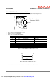
DS2100 User's Manual (Preliminary) SECTION 3: WIRING AND INSTALLATION 3.11.5 Motor Encoder Connection The DS2100 encoder input supports a variety of encoders. These include Analogue, SSI, Hiperface and Endat. The connections to the drive for each of these encoder types are given in Table 3.25. Encoder Connector Figure 3.38 Motor Encoder Connector Location - Fixed connector: 15 pin, female Sub-D connector Mating connector, 15pin male Sub-D Wiring: cable. 28-18AWG (0.14-0.
SECTION 3: WIRING AND INSTALLATION Re quire d for C E-C ompliance DS2100 User's Manual (Preliminary) For CE compliance, shield should be attached on both sides of encoder cable. NOTE:- Avoid running the encoder cable near other high power wiring, especially the motor power cable, if possible. NOTE:- Cable Length should not exceed 30m (100 feet).
DS2100 User's Manual (Preliminary) SECTION 3: WIRING AND INSTALLATION 3.11.6 Motor Rotation Direction The positive direction of rotation is clockwise, when the motor is viewed from the shaft end, as shown in the diagram below. M otor Front Clockwise is Positive Direction of Rotation Figure 3.39 Rotational Convention for Mechanical Process Variables NOTE:-. For operation with the encoder, positive rotation as defined here corresponds to Channel A leading Channel B.
SECTION 3: WIRING AND INSTALLATION DS2100 User's Manual (Preliminary) 3.12 DS2100 Control Input and Outputs The following section contains a description of the control related Input/Output (I/O) available to the user. Functionality of this I/O is detailed later in this manual. NOTE - An external 12Vd.c. to 32Vd.c. power source (user supplied) is required for the I/O functions. The amperage rating of this power source will depend on the number of I/O functions used.
DS2100 User's Manual (Preliminary) SECTION 3: WIRING AND INSTALLATION 3.12.1 General Purpose Description of the Digital Inputs The DS2100 provides 8 digital inputs on connector J2A. - Fixed connector: 9 pins, male connector Mating connector, 9 pins spring cage, female, supplied with the drive. Phoenix Contact (Part # FK-MC 0.5/9-ST2.5) Wiring: cable. 28-20AWG (0.14-0.5mm2) Wire stripping: 8 mm Name Pos. Function J2A.1 I1 Digital Input # 1 Drive Enable J2A.2 I2 Digital Input # 2 User Configurable J2A.
SECTION 3: WIRING AND INSTALLATION DS2100 User's Manual (Preliminary) Note that:§ Input Impedance > 5k W. § Voltage Range is 12V to 32V from Digital-Input to the I_COMMON line. Inputs are protected for input voltages from –40V to +40V § Input voltages whose magnitude is less than 12V with respect to the I_COMMON line will not be guaranteed to be recognised as an active signal input.
DS2100 User's Manual (Preliminary) SECTION 3: WIRING AND INSTALLATION 3.12.2 General Purpose Description of the Digital Outputs The DS2100 provides 4 digital outputs on connector J2B & J2C. Only the digital outputs on J2B are detailed here. - Fixed connector: 5 pins, male connector Mating connector, 5 pins spring cage, female, supplied with the drive. Phoenix Contact (Part # FK-MC 0.5/5-ST2.5) Wiring: cable. 28-20AWG (0.14-0.5mm2) Wire stripping: 8 mm Name Ext 24V DC O1 O2 O3 Ext 24V Ret Pos. J2B.1 J2B.
DS2100 User's Manual (Preliminary) SECTION 3: WIRING AND INSTALLATION 3.12.2.1 Drive Ready Relay The DS2100 provides 1 relay outputs on connector J2C. This relay closes when the drive is ready and no faults are present. - Fixed connector: 2 pins, male connector Mating connector, 2 pins spring cage, female, supplied with the drive. Phoenix Contact (Part # FK-MC 0.5/2-ST2.5) Wiring: cable. 28-20AWG (0.14-0.5mm2) Wire stripping: 8 mm Pos. J2C.1 J2C.
DS2100 User's Manual (Preliminary) SECTION 3: WIRING AND INSTALLATION 3.12.3 Power Sequencing on Startup The timing of the digital inputs ENABLE and PWR_RDY must be considered carefully for proper power-on sequencing. Minimum Time from Logic power to Drive Ready 6 seconds A.C. Mains to Drive Ready < 4s Logic Power applied 24Vd.c. A.C. Mains applied to DS2100 Drive Ready Relay output of DS2100 Drive Ready activated to ENABLE transition can be < 6ms ENABLE input Figure 3.
SECTION 3: WIRING AND INSTALLATION DS2100 User's Manual (Preliminary) 3.13 Communications Interface Wiring and Configuration The DS2100 provides one serial interface (RS232) for communication between the drive and the Windrive graphical user interface (GUI).
DS2100 User's Manual (Preliminary) SECTION 3: WIRING AND INSTALLATION PC 2 3 DS2100 Rx Rx Tx Tx 5 Gnd 2 3 5 Figure 3.46 DS2100's J1 RS232 Wire Pin-out The RS232 Cable shield should be connected to the metal body of the D-Type connector. 3.13.2 CAN Cable Wiring The CAN-In and CAN-Out ports at J3A and J3B of the DS2100 provide the means to daisy-chain the CAN cabling between DS2100 units and system controller. The CAN interface is equipped with driver and receiver for 24V systems.
DS2100 User's Manual (Preliminary) SECTION 3: WIRING AND INSTALLATION - Fixed connector: 9 pin, male & female Sub-D connector Mating connector, 9 pin male & female Sub-D Wiring: cable. 28-18AWG (0.14-0.82mm2) Pos (x=A,B) J3x.1 J3x.2 J3x.3 J3x.4 J3x.5 J3x.6 J3x.7 J3x.8 Signal CAN_L CAN_GND CAN_SHLD CAN_GND CAN_H - J3x.
DS2100 User's Manual (Preliminary) SECTION 3: WIRING AND INSTALLATION To Controller mPro Controller J3A CAN IN Controller J3B CAN OUT NC CAN_L CAN_H NC CAN_SHLD CAN_GND CAN_GND NC NC (V_EXT) Notes Figure 3.
SECTION 3: WIRING AND INSTALLATION DS2100 User's Manual (Preliminary) 3.14 Wiring Summary 3.14.1 mA Size Power Stage - Fixed connector: 12 pins, male connector Mating connector, 12 pins, female, supplied with the drive. Phoenix Combicon (Part # GMSTB 2.5/12-ST-7.62) mA size wiring: cable 14 AWG (2.1 mm2). Wire stripping: 7 mm. Tightening torque: 0.5Nm. Name Pos. Function J6.1 DCDC Bus (-) J6.2 DC+ DC Bus (+) J6.3 RR Regeneration Resistance J6.
DS2100 User's Manual (Preliminary) SECTION 3: WIRING AND INSTALLATION 3.14.2 A & B Size Power Stage - Fixed connector: 10 pins, male connector Mating connector, 10 pins, female, supplied with the drive. Phoenix Contact (Part # PC4 HV/10-ST-7.62) A size wiring: cable 14AWG (2.1 mm2). Wire stripping: 7 mm B size wiring: cable 12AWG (3.3 mm2). Wire stripping: 7 mm Tightening torque: 0.5Nm. Pos. J6.1 J6.2 J6.3 J6.4 J6.5 J6.6 J6.7 J6.8 J6.9 J6.
SECTION 3: WIRING AND INSTALLATION DS2100 User's Manual (Preliminary) 3.14.3 C Size Power Stage J6 J9 J8 J7 - Fixed connector: 5 pins, male connector Mating connector, 5 pins, female, crimped supplied with the drive. (Molex 42816-0512) C size wiring: cable 8 AWG (8.4 mm2). Name Pos. Function J6.1 L3 Phase "L3", ", three-phase voltage input 230/460Vac ±10% J6.2 L2 Phase "L2", ", three-phase voltage input 230/460Vac ±10% J6.3 L1 Phase "L1", three-phase voltage input 230/460Vac ±10% J6.
DS2100 User's Manual (Preliminary) SECTION 3: WIRING AND INSTALLATION 3.14.4 D Size Power Stage - Fixed connector: 4 pole, screw terminal D size wiring: cable 6 AWG (13 mm2) for 50/140 D size wiring: cable 4 AWG ( 21mm2) for 60/180 PE Terminal wiring: cable 6 AWG (13 mm2) for 50/140 PE Terminal wiring: cable 4 AWG (21 mm2) for 60/180 Stripping Length 16mm Tightening Torque: 2-2.3Nm Name Pos. Function J9.1 RR Regeneration Resistance J9.2 DC+(RR) DC Bus (+) J9.3 PE Protective Earth Screw Terminal J9.
SECTION 3: WIRING AND INSTALLATION DS2100 User's Manual (Preliminary) 3.14.
DS2100 User's Manual (Preliminary) 3.14.5.1 SECTION 3: WIRING AND INSTALLATION RS232 PC 2 3 5 - DS2100 Rx Rx Tx Tx Gnd Fixed connector: 9 pin, female Sub-D connector Mating connector, 9 pin male Sub-D Wiring: cable. 28-18AWG (0.14-0.82mm2) Name Pos. Function J1.1 connected to pin 4 J1.2 TxD Transmit Data J1.3 RxD Receive Data J1.4 connected to pin 1 and 6 J1.5 Gnd Gnd J1.6 connected to pin 4 J1.7 connected to pin 8 J1.8 connected to pin 7 J1.
DS2100 User's Manual (Preliminary) SECTION 3: WIRING AND INSTALLATION 3.14.5.4 Drive Ready - Fixed connector: 2 pins, male connector - Mating connector, 2 pins spring cage, female, supplied with the drive. Phoenix Contact (Part # FK-MC 0.5/2-ST2.5) - Wiring: cable. 28-20AWG (0.14-0.5mm2) - Wire stripping: 8 mm Pos. J2C.1 J2C.2 Name Drive Ready 1 Drive Ready 2 Function Drive ready relay contact pin 1 Drive ready relay contact pin 1 Drive Ready Relay Contact Drive Ready Relay Contact 3.14.5.
DS2100 User's Manual (Preliminary) SECTION 3: WIRING AND INSTALLATION 3.14.5.7 Encoder - Fixed connector: 15 pin, female Sub-D connector - Mating connector, 15pin male Sub-D - Wiring: cable. 28-18AWG (0.14-0.82mm2) 15-Pin Sub-D Connector Plug (male) on cable DS2100 Cable End J4 Analogue SSI J4.1 J4.2 J4.3 J4.4 J4.5 J4.6 J4.7 J4.8 J4.9 J4.10 J4.11 Shield - Sine - Cosine Gnd Supply - Channel Z (Zero) NTC/PTC + Sine + Cosine +5 V .. +12V Supply (150 mA max.
SECTION 3: WIRING AND INSTALLATION DS2100 User's Manual (Preliminary) 3.14.5.8 Resolver - Fixed connector: 9 pin, female Sub-D connector - Mating connector, 9 pin male Sub-D - Wiring: cable. 28-18AWG (0.14-0.82mm2) MOTOR RESOLVER CONNECTOR Pos Signal FAS T/ FAS N/ Type FAS K FAS Y C 1 J5.1 Cosj (S2) J5.2 E 2 (S4) Cos j G4xx (FASG) 3 4 J5.9 J5.7 J5.8 J5.6 J5.4 J5.5 V-Ref (R1) 0V (R2) PTC\NTC PTC\NTC Sinj (S1) Sin j (S3) D B N A G H 10 7 8 9 11 12 7 8 6 5 1 2 J5.