
Home Theater Server - Multiroom Video Controller User Manual


SECTION 3: WIRING AND INSTALLATION DS2100 User's Manual (Preliminary)
PAGE 3-63
3.13 Communications Interface Wiring and Configuration
The DS2100 provides one serial interface (RS232) for communication between the drive and the Windrive graphical
user interface (GUI).
The drive also provides a CAN High speed (ISO11898-2) hardware-interface for higher bandwidth communications
between one System Motion Controller and many DS2100's (which can handle motion commands between the System
Motion Controller and DS2100's)
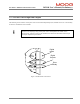
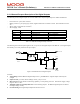
3.13.1 RS232 Serial Communications Interface
The pin assignment enables use of a 9-pin Sub-D cable with all signals connected straight through.
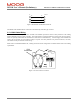
Serial Communications
Connector (RS232)
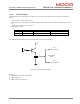
Figure 3.45 RS232 Connector Location
-
Fixed connector: 9 pin, female Sub-D connector
-
Mating connector, 9 pin male Sub-D
-
Wiring: cable. 28-18AWG (0.14-0.82mm
2
)
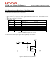
Pos.
Name
Function PC Signal
J1.1 - connected to pin 4 DCD input
J1.2 TxD Transmit Data RxD input
J1.3 RxD Receive Data TxD output
J1.4 - connected to pin 1 and 6 DTR output
J1.5 Gnd Gnd Gnd
J1.6 - connected to pin 4 DSR input
J1.7 - connected to pin 8 RTS output
J1.8 - connected to pin 7 CTS input
J1.9 - unused RI input
Table 3.29 J1, DS2100 RS232 Serial Interface Connector