
Home Theater Server - Multiroom Video Controller User Manual

SECTION 3: WIRING AND INSTALLATION DS2100 User's Manual (Preliminary)
PAGE 3-73
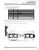
3.14.5.4 Drive Ready
-
Fixed connector: 2 pins, male connector
-
Mating connector, 2 pins spring cage, female, supplied with the drive. Phoenix Contact (Part # FK-MC 0.5/2-ST-
2.5)
-
Wiring: cable. 28-20AWG (0.14-0.5mm
2
)
-
Wire stripping: 8 mm
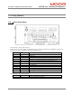
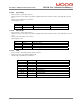
Pos.
Name
Function
J2C.1 Drive Ready 1 Drive ready relay contact pin 1 Drive Ready Relay Contact
J2C.2 Drive Ready 2 Drive ready relay contact pin 1 Drive Ready Relay Contact
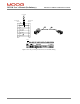
3.14.5.5 Motor Brake
-
Fixed connector: 4 pins, male connector
-
Mating connector, 4 pins spring cage, female, supplied with the drive. Phoenix Contact (Part # FK-MCP 1.5/4-ST-
3.81)
-
Wiring: cable. 28-16AWG (0.14-1.5mm
2
)
-
Wire stripping: 9 mm
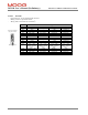
Pos.
Name
Function
J2D.1 24V DC Brake 24V Supply
J2D.2 + Brake +
J2D.3 - Brake -
J2D.4 24V RET Brake 24V Supply Return
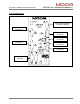
3.14.5.6 CAN
-
Fixed connector: 9 pin male & female, Sub-D connector
-
Mating connector, 9 pin male & female Sub-D
-
Wiring: cable. 28-18AWG (0.14-0.82mm
2
)
Pos (x=A,B) Signal Description
J3x.1 - not connected
J3x.2 CAN_L CAN_L bus line (dominant low)
J3x.3 CAN_GND CAN Ground
J3x.4 - not connected
J3x.5 CAN_SHLD Chassis Ground
J3x.6 CAN_GND CAN Ground
J3x.7 CAN_H CAN_H bus line (dominant high)
J3x.8 - not connected
J3x.9 - Optional CAN external positive supply, not connected.