DS2100 Digital Controller Installation & User’s Manual
D C B A Revision C27750-001 Added motor thermal protection notes following UL508C review. Updated boxcar drawing.
SECTION 1: DS2100 OVERVIEW DS2100 User's Manual SECTION 1: DS2100 OVERVIEW C27750-001 PAGE 1-1
DS2100 User's Manual SECTION 1: DS2100 OVERVIEW TABLE OF CONTENTS SECTION 1: DS2100 OVERVIEW..........................................................................................................................1-1 1.1 INTRODUCTION ..................................................................................................................................................1-3 1.2 DS2100 MODELS .........................................................................................................
SECTION 1: DS2100 OVERVIEW DS2100 User's Manual 1.1 Introduction This section gives an overview of the available DS2100 models, ratings and general specifications. Detailed outlines of installation and wiring, functionality, user interfaces and other technical data are given in subsequent sections. CAUTION: Repairs or modifications to the product by anyone other than a Moog authorised repair facility may create unsafe operating conditions and will invalidate the product warranty.
DS2100 User's Manual SECTION 1: DS2100 OVERVIEW 1.2 DS2100 Models The DS2100 family is available in nine base models, which cover a range of output current ratings. DS2100 Base Model Code Size G361-xx03 µA G361-xx06 µA G361-xx08 A G361-xx14 B G361-xx20 C G361-xx25 C G361-xx30 C G361-xx50 D G361-xx60 D G361-xx1x E Continuous (Arms) 3 6 8 14 20 25 30 50 60 100 Amplifier Current Rating Maximum (Arms) 8 16 16 29.7 31.8 49.5 63.6 99.3 127.6 212.7 Peak (A) 11 22 22 42 45 70 90 140 180 300 Table 1.
DS2100 User's Manual SECTION 1: DS2100 OVERVIEW G361 Model Series Designator Current Model Design Status X X X XX X - XX - XXX Letter E (E model) - (dash) Fieldbus / command reference No. Option Description Status 0 1 2 3 4 Reserved CAN Reserved Reserved Reserved Available - Safety Interlock No. Option 0 1 No Safety Interlock Safety Interlock installed. Power Rating Section No.
DS2100 User's Manual SECTION 1: DS2100 OVERVIEW Moog also provides and recommends a variety of accessories for the DS2100. Examples include: • EMC cable brackets for securing cable and grounding shields at the DS2100. (Supplied as standard with DS2100). • Pre-configured motor cables. • Fuses & circuit breakers for use with the DS2100 drives. • Filters to achieve EMC compliance. • Graphical User Interface (GUI) for drive configuration and diagnostics.
SECTION 1: DS2100 OVERVIEW DS2100 User's Manual 1.
DS2100 User's Manual SECTION 1: DS2100 OVERVIEW 1.4 Design Standards The DS2100 is CE-Marked under the EU's Low Voltage Directive. It has been designed to allow easy compliance of customer's machines under the EU's EMC Directive (measures as directed in this manual have to be taken to ensure EMC compliance). It is designed to the UL508C standard. The µA size DS2100 units are UL Recognised. The DS2100 A-D sizes are UL listed.
DS2100 User's Manual SECTION 1: DS2100 OVERVIEW 1.5 Power Ratings Specifications Model : G361-x 3Amp 6Amp 8Amp 14Amp 20Amp 25Amp 30Amp 50Amp 60Amp 100Amp A.C. Mains Input Range Minimum 65Vac (110Vac -40%) Maximum 506Vac (440Vac +10%) Frequency Range 50 - 60Hz Internal Regeneration Power Continuous Dissipation 50W 100W Peak Dissipation @ 230Vac 1.3Kw 1.3kW Peak Dissipation @ 400Vac 4.8kW 4.
DS2100 User's Manual 1.5.1 SECTION 1: DS2100 OVERVIEW Optional Control Logic Backup Power D.C. Bus Minimum Voltage (below which 24Vd.c. Control Logic Backup supply is needed) 24V Input 170Vd.c. (Generated from rectified 120Va.c.) 24Vd.c.± 10% 2.0A steady state Table 1.4 DS2100 Control Logic Backup Power Ratings An auxiliary 24V d.c. control logic backup supply is MANDATORY for the –x003 & -x006 variants of the DS2100 product family.
SECTION 1: DS2100 OVERVIEW DS2100 User's Manual 1.5.4.1 RMS Protection The RMS protection acts to limit the current provided to the rated continuous current of the drive. Thus, a G361-x006 cannot supply, on average, greater than 6Acontinuous RMS to the motor. The current to the motor is averaged and if it exceeds the RMS rating, the drive limits the current command.
DS2100 User's Manual SECTION 1: DS2100 OVERVIEW 1.6 General Functional Specifications 1.6.1 • • • • Digital Inputs (J2A) 8 Digital Inputs, user configurable Digital Input 1 Dedicated to High Power Enable All Optically Isolated, 12…36V Input Range. 5kΩ input impedance.
DS2100 User's Manual SECTION 1: DS2100 OVERVIEW 1.6.3 Standard I/O Brake Control (J2D) Motor Position Feedback Type (J4/J5) Communications Interfaces (J1) 1.6.4 2A, 24Vd.c. solid-state high-side drive for motor brake control. Switched under user control or DS2100 software control Resolver Encoder Types • SSI • Hiperface • Analogue encoders • Endat RS232 Interface at 19200Baud Table 1.
DS2100 User's Manual SECTION 1: DS2100 OVERVIEW Page Intentionally Blank PAGE 1-14 C27750-001
SECTION 2: SAFETY & EMC INSTRUCTIONS DS2100 User's Manual SECTION 2: SAFETY & EMC INSTRUCTIONS C27750-001 PAGE 2-1
DS2100 User's Manual SECTION 2: SAFETY & EMC INSTRUCTIONS TABLE OF CONTENTS SECTION 2: SAFETY & EMC INSTRUCTIONS................................................................................................. 2-1 2.1 GENERAL........................................................................................................................................................... 2-3 2.2 SAFETY REGULATIONS ....................................................................................................
SECTION 2: SAFETY & EMC INSTRUCTIONS DS2100 User's Manual 2.1 General This user’s manual is intended to provide sufficient information on how to install Moog DS2100 electric motor systems. Section 2.2 covers Safety and System Safeguards. Section 2.3 covers Electromagnetic Compatibility (EMC). This user’s guide must be read and understood before applying power and operating the equipment described. This equipment must be installed and serviced only by duly qualified service personnel.
DS2100 User's Manual 2.2 SECTION 2: SAFETY & EMC INSTRUCTIONS Safety Regulations 1. The DS2100 controller must be disconnected from all power if repair work is to be carried out. Check that the mains supply has been disconnected and that at least 5 minutes has passed for the µA size (6 minutes for A-E sizes), to allow for D.C. bus capacitors to discharge, before removing motor and mains connections. 2.
SECTION 2: SAFETY & EMC INSTRUCTIONS 2.2.1 DS2100 User's Manual System Safeguards a) General Safety Requirements Users are required to implement safety measures with all equipment, systems and installations into which the DS2100 Servo-drive are installed. In addition, safeguards must be an integral part of workcell design, installation, operator training and operator procedures where this equipment is used.
DS2100 User's Manual SECTION 2: SAFETY & EMC INSTRUCTIONS A D.C component can occur in the fault current in the event of a fault connection to earth. Only a residual-currentoperated protective device (RCD) of Type B is allowed. When the protection in installations with regard to indirect contact is achieved by means of an RCD, their appropriate function/combination shall be verified.
DS2100 User's Manual SECTION 2: SAFETY & EMC INSTRUCTIONS DS2100 Models Size µA Size 3/11 6/22 Short Circuit Rating Notes 5,000 Ampsrms Power Line Fuse 25A, 660V FWP25-A1F Semiconductor (Cooper Bussmann) Recovery Resistor Fuse Contact Moog Application Engineering for Advice 24Vdc Auxiliary Power Supply Fuse 3A, 250V DS2100 Models Size Delayed Size A Size B 8/22 14/42 Short Circuit Rating Notes 5,000 Ampsrms Power Line Fuse 50-FE 690V Semiconductor (Cooper Bussmann) Recovery Resi
DS2100 User's Manual 2.2.2 SECTION 2: SAFETY & EMC INSTRUCTIONS Equipment Safety All persons must observe sound safety practices during the operation and testing of all electrically powered equipment. Prior to first use, power should not be applied to the DS2100 Servo-drive until all instructions in the Wiring and Installation section of this User’s manual have been carried out. WARNING - DO NOT remove or replace any assemblies, subassemblies or components with primary power present.
SECTION 2: SAFETY & EMC INSTRUCTIONS DS2100 User's Manual Safeguards should be an integral part of a work cell design, installation, operator training, and operator procedures. A computer-controlled system may activate remote devices under program control at times not anticipated by personnel. It is critical that safeguards be in place to prevent personnel from entering the work cell whenever equipment power is present.
DS2100 User's Manual 2.2.3 SECTION 2: SAFETY & EMC INSTRUCTIONS Safety Requirements for Cables Required for CE-Compliance User's whose machine installations require CECompliance should read this Section. a) Requirements - Conductors and Cables All cables and conductors used shall be specified as compliant with the requirements of European Standard EN 60204-1 and other known National and International Standards for the environment in which they are installed and for the voltage and current carried.
DS2100 User's Manual SECTION 2: SAFETY & EMC INSTRUCTIONS The following table details the recommended cable dimensions for all DS2100 models DS2100 Models Notes A µA B 3/11 AWG (mm2) 6/22 AWG (mm2) 8/22 AWG (mm2) 14/42 AWG (mm2) Line Power 3x14 (2.1) 3x14 (2.1) 3x14 (2.1) 3x12 (3.3) Protective Bonding Cable 1x 6 (13) 1x 6 (13) 1x 6 (13) 1x 6 (13) Motor Power Cable 4x14 (2.1) 4x14 (2.1) 4x14 (2.1) 4x12 (3.31) Shielded Regen Resistor Cable 2x14 (2.1) 2x14 (2.1) 2x14 (2.
DS2100 User's Manual SECTION 2: SAFETY & EMC INSTRUCTIONS Wherever possible, insulated conductors and cables that have flame-retardant properties shall be used. Where insulated conductors and cables can constitute a fire hazard due to the propagation of a fire or the emission of toxic or corrosive fumes (e.g. PVC), guidance from the cable supplier should be sought. In particular it is important to maintain the integrity of circuits having a safety function (e.g.
SECTION 2: SAFETY & EMC INSTRUCTIONS DS2100 User's Manual f) Wiring Practices - Identification of the protective conductor The protective conductor shall be readily distinguishable by shape, location, marking or colour. When identification is by colour alone, the bicolour combination GREEN-AND-YELLOW shall be used throughout the length of the conductor. This colour identification is strictly reserved for the protective conductor.
DS2100 User's Manual SECTION 2: SAFETY & EMC INSTRUCTIONS Flexible conduit or flexible multi-conductor cable shall be used where it is necessary to employ flexible connections to pendant push-button stations. The weight of pendant stations shall be supported by means other than the flexible conduit or the flexible multi-conductor cable, except where the conduit or cable is specifically designed for that purpose.
SECTION 2: SAFETY & EMC INSTRUCTIONS 2.2.4 DS2100 User's Manual EMC requirements for cables User's whose machine installations require for CECompliance should read this Section. Required for CE-Compliance Avoid close parallel routing of signal cables and power cables. Always use the minimum length of cable necessary and install all cables in a fixed routing. Data signal cables, motor power and resolver/signal cables, regen resistor cables and power input cables shall have segregated routings.
DS2100 User's Manual SECTION 2: SAFETY & EMC INSTRUCTIONS 2.3 Electromagnetic Compatibility (EMC) Required for CE-Compliance User's whose machine installations are intended for CECompliance should read this Section. The DS2100 Servo-drive are system components which must be installed in a correct manner to ensure that all electromagnetic compatibility (EMC) requirements are met.
DS2100 User's Manual SECTION 2: SAFETY & EMC INSTRUCTIONS Shielded cable is required to be installed by the user for many external user cable connections to the DS2100. Details of areas where shielded cable must be installed and details of earthing arrangements which must be implemented for the shields of such cables are given throughout Section 3 of this User’s Guide.
DS2100 User's Manual SECTION 2: SAFETY & EMC INSTRUCTIONS The following table details the mechanical dimensions of the recommended filters. Moog Order Code AT6017 AT6009 AT6010 AT6011 AT6012 AT6013 AT6015 Manufacturer Schaffner FN2070-3-06 Schaffner FN 258-7/07 Schaffner FN35012/29 Schaffner FN25816/07 Schaffner FN25830/07 Schaffner FN25842/07 Schaffner FN25855/07 Schaffner FN258100/35 Dimensions [mm] L4 L5 0 65 L1 85 L2 75 L3 54 255 240 50 25 99.5 51 105 95 3.
SECTION 2: SAFETY & EMC INSTRUCTIONS DS2100 User's Manual EMC filter can produce high leakage currents to ground (Protective Earth). The current levels associated with individual filters are detailed in the associated filter datasheet. CAUTION: The filter must be connected to earth before connecting the supply. WARNING: High voltage –Internal filter capacitors discharge time: approx. 10 seconds. 2.3.
DS2100 User's Manual SECTION 2: SAFETY & EMC INSTRUCTIONS All external Regen (Regenerative circuit) resistors used with the DS2100 must be installed in conductive enclosures which provide a degree of ingress protection against liquids and objects of at least IP22. Any paint on the panel or regen resistor enclosure must be removed before the regen resistor enclosure is mounted. Cables supplying external d.c. supply voltages to the DS2100 Servo-drive (For example, the 24 Vd.c.
SECTION 2: SAFETY & EMC INSTRUCTIONS DS2100 User's Manual Figure 2.
DS2100 User's Manual SECTION 2: SAFETY & EMC INSTRUCTIONS Figure 2.
SECTION 2: SAFETY & EMC INSTRUCTIONS DS2100 User's Manual Figure 2.
DS2100 User's Manual SECTION 2: SAFETY & EMC INSTRUCTIONS Figure 2.
SECTION 2: SAFETY & EMC INSTRUCTIONS DS2100 User's Manual Figure 2.
DS2100 User's Manual SECTION 2: SAFETY & EMC INSTRUCTIONS 2.4 UL Requirements Detailed below are the specific UL requirements for the DS2100. 2.4.1 Specific UL Requirements • Usage: The DS2100 shall be used according to the guidelines given in this manual. • Ratings: The DS2100 shall be used within the ratings specified in the markings on the equipment. • 24V Logic Supply: The 24V supply is intended for use in the secondary of a Class 2 supply.
SECTION 2: SAFETY & EMC INSTRUCTIONS DS2100 User's Manual • Motor Overload Protection: The DS2100 does not incorporate an internal motor load protection. The drive is intended to be used with motors that have integral thermal protection in the form of an NTC or PTC thermistor. The selections of NTC or PTC and overtemperature fault level are set in software. See ‘Motor Thermal Parameters’ and ‘Motor Thermal Protection Mechanism’ in Section 5 of this manual.
DS2100 User's Manual SECTION 2: SAFETY & EMC INSTRUCTIONS Page Intentionally Blank PAGE 2-28 C27750-001
SECTION 3: WIRING AND INSTALLATION SECTION 3: C27750-001 DS2100 User's Manual WIRING AND INSTALLATION PAGE 3-1
DS2100 User's Manual SECTION 3: WIRING AND INSTALLATION TABLE OF CONTENTS SECTION 3: WIRING AND INSTALLATION ................................................................................................. 3-1 3.1 System Components .................................................................................................................................. 3-4 3.1.1 A.C. Mains Power Interface..............................................................................................................
SECTION 3: WIRING AND INSTALLATION 3.14.5 3.14.6 C27750-001 DS2100 User's Manual E Size Power Stage...........................................................................................................................3-77 Control Card .....................................................................................................................................
DS2100 User's Manual SECTION 3: WIRING AND INSTALLATION This section covers the installation, wiring and cabling of the Moog DS2100 Servo-drive series. A pictorial diagram of a single-axis system, with typical components included, is shown in Figure 3.1. Users are directed to read Section 2, Safety Instructions, before proceeding with wiring and installation.
SECTION 3: WIRING AND INSTALLATION DS2100 User's Manual 3.1.2 A.C. Input Line Protection Details of the recommended Line fuses are given in Section 2 of this manual. Alternatively an AC mains Circuit Breaker (Instantaneous Trip Type) can be used as a protective device providing its ratings are equivalent to the recommended fuses.
DS2100 User's Manual SECTION 3: WIRING AND INSTALLATION Figure 3.
SECTION 3: WIRING AND INSTALLATION DS2100 User's Manual 3.1.4 Serial Set-up Terminal (User-Supplied) An RS-232 interface should be established for individual servo-drive communications, using a PC. The PC can run Moog's WinDrive Windows-based user-interface program.
DS2100 User's Manual 3.1.6.1 SECTION 3: WIRING AND INSTALLATION Brushless Motor Brake 24V Power Supply The motor brake requires a 24Vdc supply for release. This should be rated to cover at least twice the sums of the rated currents of all brakes connected. 3.1.7 Heatsinks and Climatic Control The need for air conditioning will depend on the duty cycle of the system and the surrounding ambient temperature. The maximum allowable ambient temperature is 40°C (104°F).
SECTION 3: WIRING AND INSTALLATION DS2100 User's Manual 3.2 Equipment Mounting This section details the mechanical dimensions of the DS2100 chassis, as well as required clearances for cabling etc. The DS2100 is designed to be panel or cabinet mounted. The DS2100 must be mounted in a vertical orientation. The DS2100 must be panel mounted within an enclosure or cabinet that provides a degree of ingress protection against liquids and objects of at least IP54.
DS2100 User's Manual SECTION 3: WIRING AND INSTALLATION Figure 3.2 Typical DS2100 Cable Bend Radius Requirements The DS2100 must be permanently and reliably connected to Earth and all conductive parts in the IP54 rated enclosure or cabinet must be permanently connected to Earth. The impedance between the earth terminal and any accessible part of the enclosure or cabinet should be less than or equal to 0.1 Ω.
DS2100 User's Manual SECTION 3: WIRING AND INSTALLATION Figure 3.
DS2100 User's Manual SECTION 3: WIRING AND INSTALLATION Figure 3.
DS2100 User's Manual SECTION 3: WIRING AND INSTALLATION Figure 3.
DS2100 User's Manual SECTION 3: WIRING AND INSTALLATION Figure 3.
DS2100 User's Manual SECTION 3: WIRING AND INSTALLATION Figure 3.
DS2100 User's Manual SECTION 3: WIRING AND INSTALLATION Figure 3.
SECTION 3: WIRING AND INSTALLATION DS2100 User's Manual 3.2.1 CE Items for Mechanical Installation Additional electromagnetic compatibility (EMC) measures must be installed on equipment associated with the DS2100 Servo-drive.
DS2100 User's Manual SECTION 3: WIRING AND INSTALLATION 3.3 Power Dissipation To calculate cabinet cooling requirements, Table 3.3-2 provides approximate equipment power dissipation values. If the application employs regeneration, be sure to add the regen resistor power dissipation to the numbers quoted in Table 3.3-2 below, (use the continuous wattage rating of the regen resistor if the actual application regen dissipation is unknown).
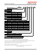
SECTION 3: WIRING AND INSTALLATION DS2100 User's Manual 3.4 DS2100 Connector Terminals Figure 3.9 to Figure 3.14 below detail the connectors on the DS2100 (all sizes). Serial Communications Connector (RS232) Motor Resolver Connector Digital Input Connector Digital Output Connector Motor Encoder Connector Drive Ready Relay Connector Motor Brake Connector CAN Field Bus Interface Figure 3.
DS2100 User's Manual SECTION 3: WIRING AND INSTALLATION Figure 3.10 DS2100 Size µA Power Connector Terminals Figure 3.
SECTION 3: WIRING AND INSTALLATION DS2100 User's Manual J6 J9 J8 J7 Figure 3.
DS2100 User's Manual SECTION 3: WIRING AND INSTALLATION Figure 3.13 DS2100 Size D Power Connector Terminals Figure 3.
SECTION 3: WIRING AND INSTALLATION DS2100 User's Manual 3.5 General System Wiring Guidelines The following is a general reminder of the cable requirements for the DS2100 Series Servo-drives and related equipment. NOTE - Cabling and component wiring is critical in obtaining successful operation of the system. Pay close attention to specified wiring practice, cabling information, earthing and shielding requirements. Improper wiring can result in electrical noise generation and unstable motor performance.
DS2100 User's Manual SECTION 3: WIRING AND INSTALLATION CAUTION - All external electrical wiring connected to this equipment must be color coded in accordance with European Standard EN 60204-1 requirements. Required for CE-Compliance CAUTION - Additional electromagnetic compatibility (EMC) measures which must be installed on equipment cables associated with the DS2100 Servo-drive are given in Section 2 of this User’s Guide.
SECTION 3: WIRING AND INSTALLATION DS2100 User's Manual 3.5.2 Wiring notes for J6, J7, J9 connectors (Size C) The connectors used on the DS2100 Size C are are formed using crimp terminals. The appropriate crimps (Molex type 42815-0031) are supplied together the floating connectors for J6, J7, and J9. These crimps are sized for an 8 AWG (8.4 mm2) cable with a 10 mm wire stripping. It is recommended to use the appropriate Molex crimping tool (63814-0000, or 63811-1500, or equivalent).
DS2100 User's Manual 3.6 SECTION 3: WIRING AND INSTALLATION Sequence of Component Wiring Recommendations The following sequence for wiring is a recommendation. Individual wiring steps are denoted by a box character, which can be used as an installation check off list. The terminal block layout on all power supplies and servo-drives has been designed to isolate low voltage from high voltage circuits. Cabinet conduits should be arranged to maintain this physical separation.
SECTION 3: WIRING AND INSTALLATION DS2100 User's Manual 3.7 Three-Phase A.C. Mains Power Source Configuration The DS2100 may be supplied from a three-phase a.c. mains input. In this case the following user supplied options are required:1. Three-Phase Mains Fusing 2. Mains Line Filter 3. 24Vd.c. Power Source & Fuse 4. 24V d.c. EMC Filter Note that for DS2100 sizes A,B,C, D & E, if the a.c.
DS2100 User's Manual AC Mains Supply 24V Supply SECTION 3: WIRING AND INSTALLATION Mounting Backplane Line Fuses Contactor 24V Supply Fuse 24V EMC Filter Line Filter 3-Phase Supply & Protective Earth System Controller DC Bus Sharing DS2100 DS2100 Notes 1) Keep all cables as short as possible. 2) Use Shielded\armoured cables 3) Ensure good HF bond to earth or chassis Regeneration Resistor Motor Position Feedback Cable Motor Position Feedback Cable Figure 3.
DS2100 User's Manual SECTION 3: WIRING AND INSTALLATION 3.7.1 AC Mains Power Source Connection 3.7.1.1 Size µA a.c. Mains L1 EMC Filter, Fuses etc. L2 L3 Protective Earth See Section 2 Installation 4 5 L1 L2 6 L3 Connector J6 PE Stud 4 5 6 L1 L2 L3 PE Stud Connector J6 µA µA Figure 3.17 µA AC Mains Input Connection - Fixed connector: 12 pins, male connector Mating connector, 12 pins, female, supplied with the drive. Phoenix Combicon (Part # GMSTB 2.5/12-ST-7.
DS2100 User's Manual 3.7.1.2 SECTION 3: WIRING AND INSTALLATION Size A & B a.c. Mains L1 EMC Filter, Fuses etc. L2 L3 Protective Earth See Section 2 Installation 5 6 L1 L2 4 L3 PE Stud Connector J6 Α&Β Figure 3.18 A & B AC Mains Input Connection - Fixed connector: 10 pins, male connector Mating connector, 10 pins, female, supplied with the drive. Phoenix Contact (Part # PC4 HV/10-ST-7.62) A size wiring: cable 14AWG (2.1 mm2). Wire stripping: 7 mm B size wiring: cable 12AWG (3.3 mm2).
DS2100 User's Manual SECTION 3: WIRING AND INSTALLATION 3.7.1.3 Size C a.c. Mains L1 EMC Filter, Fuses etc. L2 L3 Protective Earth See Section 2 Installation 2 1 L1 L2 3 L3 PE Stud Connector J6 C Figure 3.19 Size C AC Mains Input Connection - Fixed connector: 5 pins, male connector Mating connector, 5 pins, female, crimped supplied with the drive. (Molex 42816-0512) C size wiring: cable 8 AWG (8.4 mm2). PE Stud wiring: cable 6 AWG (13mm2) Pos. J6.3 J6.2 J6.
DS2100 User's Manual 3.7.1.4 SECTION 3: WIRING AND INSTALLATION Size D a.c. Mains L1 EMC Filter, Fuses etc. L2 L3 Protective Earth See Section 2 Installation 4 5 6 L1 L2 L3 3 PE Connector J9 D Figure 3.
DS2100 User's Manual SECTION 3: WIRING AND INSTALLATION 3.7.1.5 Size E a.c. Mains L1 EMC Filter, Fuses etc. L2 L3 Protective Earth See Section 2 Installation 4 5 6 L1 L2 L3 3 PE Connector J9 D Figure 3.21 Size E AC Mains Input Connection - Fixed connector: 4 pole, screw terminal E size wiring: cable 1 AWG (42 mm2) for 310/300 PE Terminal wiring: cable 1 AWG (42 mm2) for 100/300 Stripping Length 16mm Tightening Torque: 2-2.3Nm Pos. J9.3 J9.4 J9.5 J9.
DS2100 User's Manual SECTION 3: WIRING AND INSTALLATION 3.8 24V Backup Connection The DS2100 is equipped with a 24V logic supply backup. This backup supply provides logic power to the drive when AC mains power is removed. For the µA size, this backup is mandatory for drive operation. 3.8.1 Size µA 24V Input Connection 24V Auxiliary Supply Fuse Fairrite Clamp Core p/n # 00443164151 (4-Turns of Supply cable) +24V GND (0V) 11 12 11 12 Connector J6 Connector J6 µDS µDS Figure 3.
DS2100 User's Manual SECTION 3: WIRING AND INSTALLATION 3.8.2 Size A,B,C, D & E 24V Input Connection 24V Auxiliary Supply Fuse +24V GND (0V) Schaffner FN2070-3-06 Filter 1 2 Connector J8 A,B,C, D & E Figure 3.23 Size A,B, C, D & E 24V DC Input Connection - Fixed connector: 2 pins, male connector Mating connector, 2 pins, female, supplied with the drive. Wago (Part # 231-102/026-000) A,B,C & D size wiring: cable 14 AWG (2.1 mm2). Stripping Length 8mm Pos. J8.1 J8.
DS2100 User's Manual SECTION 3: WIRING AND INSTALLATION 3.8.3 Auxiliary 24V Fan connection (Size E) 24V Auxiliary Supply +24V GND (0V) 1 2 Connector J8 Size E Figure 3.24 Size E auxiliary 24V fan supply - Fixed connector: 2 pole, screw terminal Cable 14 AWG (2.1 mm2) Stripping 9mm Torque 0.
DS2100 User's Manual SECTION 3: WIRING AND INSTALLATION 3.9 Paralleling DS2100 Units through the D.C. Bus DS2100 units can be paralleled via the D.C. Bus, in order to share regeneration power. To comply with the EMC Directive, the DC Bus cable must be shielded and the shield must be connected to the housing with a 360o connection at both ends. Required for CE-Compliance CAUTION – To connect drives through the DC bus, please contact Moog application engineering for advice. 3.9.
DS2100 User's Manual SECTION 3: WIRING AND INSTALLATION Name DCDC+ Pos. J6.1 J6.2 Function DC Bus (-) DC Bus (+) Table 3.3-9 J6, DC Bus connector, µA Size 3.9.2 A & B Size DC Bus Inter-connection a.c. Mains L1 L2 L3 Protective Earth Tie screen to chassis via EMC bracket. See Section 2 L1 L2 L3 PE (J6.4)(J6.5)(J6.6) Stud DC- DC+ (J6.1) (J6.2) Connector J6 DS2100 A & B L1 L2 L3 PE (J6.4)(J6.5)(J6.6) Stud DC- DC+ (J6.1) (J6.2) Connector J6 DS2100 A & B Figure 3.
DS2100 User's Manual SECTION 3: WIRING AND INSTALLATION 3.9.3 C Size DC Bus Inter-connection a.c. Mains L1 L2 L3 Protective Earth Tie screen to chassis via EMC bracket. See Section 2 L1 L2 L3 PE (J6.3)(J6.2)(J6.1) Stud DC+ DC(J9.2) (J9.1) Connector J6, J9 DS2100 C L1 L2 L3 PE (J6.3)(J6.2)(J6.1) Stud DC+ DC(J9.2) (J9.1) Connector J6, J9 DS2100 C Figure 3.
DS2100 User's Manual SECTION 3: WIRING AND INSTALLATION 3.9.4 D Size DC Bus Inter-connection a.c. Mains L1 L2 L3 Protective Earth Tie screen to chassis via EMC bracket. See Section 2 L1 L2 L3 PE (J9.4)(J9.5)(J9.6) (J9.3) DC+ DC(J9.11) (J9.12) Connector J9 DS2100 D L1 L2 L3 PE (J9.4)(J9.5)(J9.6) (J9.3) DC+ DC(J9.11) (J9.12) Connector J9 DS2100 D Figure 3.
DS2100 User's Manual SECTION 3: WIRING AND INSTALLATION 3.9.5 E Size DC Bus Inter-connection a.c. Mains L1 L2 L3 Protective Earth Tie screen to chassis via EMC bracket. See Section 2 L1 L2 L3 PE (J9.6)(J9.7)(J9.8) (J9.5) DC+ DC(J9.13) (J9.14) L1 L2 L3 PE (J9.6)(J9.7)(J9.8) (J9.5) DC+ DC(J9.13) (J9.14) Connector J9 Connector J9 DS2100 E DS2100 E Figure 3.
DS2100 User's Manual SECTION 3: WIRING AND INSTALLATION 3.10 Internal/External Regeneration (Regen) Resistors – Configurations Regeneration resistors can be fitted to all DS2100 servo-drives. All external Regen resistors should be mounted to allow adequate heat dissipation and such that heat from the Regen resistor is not directed to air intakes of other equipment. The µA size DS2100 is the only size with internal regen. All other drive sizes use external regen only.
SECTION 3: WIRING AND INSTALLATION DS2100 User's Manual 3.10.1 µA Size Regeneration Resistor Connection Recovery Resistor J6.2 J6.3 DC+ RR Tie Screen to chassis via EMC bracket. See Section 2 Installation Tie screen to panel on which resistor is mounted. Connector J6 DS2100 µA Figure 3.3.30 DS2100 Size µA External Regeneration Connections - Fixed connector: 12 pins, male connector Mating connector, 12 pins, female, supplied with the drive. Phoenix Combicon (Part # GMSTB 2.5/12-ST-7.
DS2100 User's Manual - SECTION 3: WIRING AND INSTALLATION Fixed connector: 10 pins, male connector Mating connector, 10 pins, female, supplied with the drive. Phoenix Contact (Part # PC4 HV/10-ST-7.62) A size wiring: cable 14AWG (2.1 mm2). Wire stripping: 7 mm B size wiring: cable 14AWG (2.1 mm2). Wire stripping: 7 mm Tightening torque: 0.5Nm. Pos. J6.2 J6.3 Name DC+ RR Function DC Bus (+) Regeneration Resistor Table 3.3-16 J6, Regeneration Resistor connector, A,B Size 3.10.
SECTION 3: WIRING AND INSTALLATION DS2100 User's Manual 3.10.4 D Size Regeneration Resistor connection Recovery Resistor J9.2 J9.1 DC+(RR) RR Tie Screen to chassis via EMC bracket. See Section 2 Installation Tie screen to panel on which resistor is mounted. Connector J9 DS2100 D Figure 3.3.
DS2100 User's Manual SECTION 3: WIRING AND INSTALLATION 3.10.5 E Size Regeneration Resistor connection Recovery Resistor J9.4 J9.3 DC+(RR) RR Tie Screen to chassis via EMC bracket. See Section 2 Installation Tie screen to panel on which resistor is mounted. Connector J9 DS2100 E Figure 3.3.34 DS2100 Size E External Regeneration Connections J9 - Fixed connector: 2 pole, screw terminal E size wiring: cable 2 AWG (34 mm2) Stripping Length 19mm Tightening Torque: 4Nm Pos. J9.3 J9.
SECTION 3: WIRING AND INSTALLATION DS2100 User's Manual 3.11 Motors - Installation Motors should be sized by qualified personnel. Improper sizing will directly affect performance and reliability. Motor performance data for Moog motors is shown in separate data sheets. Contact Moog Applications Engineering for detailed motor technical information and application sizing, etc. Standard motors should not be mounted directly onto a gearbox with the shaft inside the lubrication chamber.
DS2100 User's Manual SECTION 3: WIRING AND INSTALLATION 3.11.2 Motor Power Cable Wire the motor power connector in accordance with Figure 3.3.35 to Figure 3.3.42. Use wire sizes based on the motor’s continuous stall current (r m s) and wire length requirements. Required for CE-Compliance Wiring must be in accordance with standard EN 60204-1 (See Section 2 of this Users Manual.
DS2100 User's Manual SECTION 3: WIRING AND INSTALLATION 3.11.2.1 Size µA DS2100 µA Motor U U (J6.10) V V (J6.9) W W (J6.8) PE PE (J6.7) J6 grounding of shield via connector clamp (or RF connection to ground screw in case of terminal board) grounding of shield via connector clamp Figure 3.3.35 DS2100 µA Motor Power Connection - Fixed connector: 12 pins, male connector Mating connector, 12 pins, female, supplied with the drive. Phoenix Combicon (Part # GMSTB 2.5/12-ST-7.
DS2100 User's Manual 3.11.2.2 SECTION 3: WIRING AND INSTALLATION Size A & B DS2100 A, B Motor U U (J6.10) V V (J6.9) W W (J6.8) PE GND (J6.7) J6 grounding of shield via connector clamp (or RF connection to ground screw in case of terminal board) grounding of shield via connector clamp Figure 3.3.36 DS2100 A & B Motor Power Connection - Fixed connector: 10 pins, male connector Mating connector, 10 pins, female, supplied with the drive. Phoenix Contact (Part # PC4 HV/10-ST-7.
DS2100 User's Manual SECTION 3: WIRING AND INSTALLATION 3.11.2.3 Size C DS2100 C Motor U U (J7.1) V V (J7.2) W W (J7.3) PE PE (J7.4) J7 grounding of shield via connector clamp (or RF connection to ground screw in case of terminal board) grounding of shield via connector clamp Figure 3.3.37 DS2100 C Motor Power Connection - Fixed connector: 4 pins, male connector Mating connector, 4 pins, female, crimped supplied with the drive. (Molex 42816-0412) C size wiring: cable 8 AWG (8.4 mm2). Pos.
DS2100 User's Manual 3.11.2.4 SECTION 3: WIRING AND INSTALLATION Size D DS2100 D Motor U U (J9.1) V V (J9.2) W W (J9.3) PE PE (J9.4) J9 grounding of shield via connector clamp (or RF connection to ground screw in case of terminal board) grounding of shield via connector clamp Figure 3.3.
DS2100 User's Manual SECTION 3: WIRING AND INSTALLATION 3.11.2.5 Size E DS2100 E Motor U U (J9.10) V V (J9.11) W W (J9.12) PE PE (J9.9) J9 grounding of shield via connector clamp (or RF connection to ground screw in case of terminal board) gr ounding of shield via connector clamp Figure 3.3.39 DS2100 E Motor Power Connection J9 - Fixed connector: 4 pole, screw terminal E size wiring: cable 1 AWG (42 mm2) Stripping Length 24mm Tightening Torque: 8Nm Pos. J9.9 J9.12 J9.11 J9.
DS2100 User's Manual SECTION 3: WIRING AND INSTALLATION 3.11.3 Motor Brake Connection The DS2100 provides a motor break relay at connector J2D (on Control Card Interface). The user supplies a 24Vd.c., Power Supply Unit for the brake connections. Details of the motor brake current requirements are available from the relevant motor datasheet. Motor Brake Connector Figure 3.3.40 Motor Brake Connector Location User Supplied 24V PSU Motor Power Cable * J2D 1 24V DC 2 + 3 4 24V RET Figure 3.3.
DS2100 User's Manual SECTION 3: WIRING AND INSTALLATION DS2100 J6 (µA, A,B), J7 (C), J9 (D,E) EMC Bracket J2D.2 J2D.3 A G H F E F B C G E D D PT00E16-8PC2 A A D B C C 97B 3100 RS 24-10P 97B 3102R 36-5P A E B A B B C D D C PT0014-5PC 97B 3102R 24-22P Figure 3.3.
DS2100 User's Manual SECTION 3: WIRING AND INSTALLATION DS2100 G4x2/3/4 G4x5 G4x6 U V W Brake+ Brake- 2 4 1 5 6 U V W + - U V W + - PT00E 168-PC2 D A B C E F 97B3100R S 24-10P D A B C E F 97B3102R 36-SP D A B C - PT00E 145 PC D A B C - 97B3102R S 24-22P D A B C - Table 3.
SECTION 3: WIRING AND INSTALLATION DS2100 User's Manual 3.11.4 Motor Resolver Connection Wire the DS2100 resolver cable in accordance with Figure 3.3.44 and Table 3.3-27. Required for CE-Compliance For CE compliance, shield should be attached on both sides of resolver cable. NOTE:- Avoid running the resolver cable near other high power wiring, especially the motor power cable, if possible. NOTE:- Cable Length should not exceed 30m (100 feet).
DS2100 User's Manual SECTION 3: WIRING AND INSTALLATION Resolver Connector Figure 3.3.43 Motor Resolver Connector Location - Fixed connector: 9 pin, female Sub-D connector Mating connector, 9 pin male Sub-D Wiring: cable. 28-18AWG (0.14-0.82mm2) Pos J5.1 J5.2 J5.9 J5.7 J5.8 J5.6 J5.4 J5.5 J5.
DS2100 User's Manual SECTION 3: WIRING AND INSTALLATION 4 S1 5 S3 1 2 1 2 3 4 5 6 7 8 S2 S4 6 NTC 8 NTC 9 R1 7 R2 S1 S3 S2 S4 NTC NTC R1 R2 PE DS2100 Cable End Motor Cable End for MOOG motors G4xx Connector PT 00E 14-19 PC-10, PT06F 8AG 14-19S 1 2 cos cos 9 V-ref 7 0V 8 PTC 6 PTC 4 sin 5 sin 3 M L K A N U J P V T H C R S G C cos E cos D V-ref B 0V B D E F shield N A G H PTC PTC sin sin S shield Motor Cable End for MOOG motors FAST & FASK DS2100 Cable End Connector IPS02A 12-12
DS2100 User's Manual SECTION 3: WIRING AND INSTALLATION 3.11.5 Motor Encoder Connection The DS2100 encoder input supports a variety of encoders. These include Analogue, SSI, Hiperface and Endat. The connections to the drive for each of these encoder types are given in Table 3.3-28. Encoder Connector Figure 3.3.45 Motor Encoder Connector Location - Fixed connector: 15 pin, female Sub-D connector Mating connector, 15pin male Sub-D Wiring: cable. 28-18AWG (0.14-0.
SECTION 3: WIRING AND INSTALLATION Re quire d for C E-C ompliance DS2100 User's Manual For CE compliance, shield should be attached on both sides of encoder cable. NOTE:- Avoid running the encoder cable near other high power wiring, especially the motor power cable, if possible. NOTE:- Cable Length should not exceed 30m (100 feet).
DS2100 User's Manual SECTION 3: WIRING AND INSTALLATION 3.11.6 Motor Rotation Direction The positive direction of rotation is clockwise, when the motor is viewed from the shaft end, as shown in the diagram below. M otor Front Clockwise is Positive Direction of Rotation Figure 3.3.46 Rotational Convention for Mechanical Process Variables NOTE:-. For operation with the encoder, positive rotation as defined here corresponds to Channel A leading Channel B.
DS2100 User's Manual SECTION 3: WIRING AND INSTALLATION 3.12 DS2100 Control Input and Outputs The following section contains a description of the control related Input/Output (I/O) available to the user. Functionality of this I/O is detailed later in this manual. NOTE - An external 12Vd.c. to 32Vd.c. power source (user supplied) is required for the I/O functions. The amperage rating of this power source will depend on the number of I/O functions used.
DS2100 User's Manual SECTION 3: WIRING AND INSTALLATION 3.12.1 General Purpose Description of the Digital Inputs The DS2100 provides 8 digital inputs on connector J2A. - Fixed connector: 9 pins, male connector Mating connector, 9 pins spring cage, female, supplied with the drive. Phoenix Contact (Part # FK-MC 0.5/9-ST2.5) Wiring: cable. 28-20AWG (0.14-0.5mm2) Wire stripping: 8 mm Name Pos. Function J2A.1 I1 Digital Input # 1 Drive Enable J2A.2 I2 Digital Input # 2 User Configurable J2A.
SECTION 3: WIRING AND INSTALLATION DS2100 User's Manual Note that: Input Impedance > 5k Ω. Voltage Range is 12V to 32V from Digital-Input to the I_COMMON line. Inputs are protected for input voltages from –40V to +40V Input voltages whose magnitude is less than 12V with respect to the I_COMMON line will not be guaranteed to be recognised as an active signal input.
DS2100 User's Manual SECTION 3: WIRING AND INSTALLATION 3.12.2 General Purpose Description of the Digital Outputs The DS2100 provides 4 digital outputs on connector J2B & J2C. Only the digital outputs on J2B are detailed here. - Fixed connector: 5 pins, male connector Mating connector, 5 pins spring cage, female, supplied with the drive. Phoenix Contact (Part # FK-MC 0.5/5-ST2.5) Wiring: cable. 28-20AWG (0.14-0.5mm2) Wire stripping: 8 mm Name Ext 24V DC O1 O2 O3 Ext 24V Ret Pos. J2B.1 J2B.2 J2B.3 J2B.
DS2100 User's Manual SECTION 3: WIRING AND INSTALLATION 3.12.2.1 Drive Ready Relay The DS2100 provides 1 relay output on connector J2C. This relay closes when the drive is ready and no faults are present. - Fixed connector: 2 pins, male connector Mating connector, 2 pins spring cage, female, supplied with the drive. Phoenix Contact (Part # FK-MC 0.5/2-ST2.5) Wiring: cable. 28-20AWG (0.14-0.5mm2) Wire stripping: 8 mm Pos. J2C.1 J2C.
DS2100 User's Manual SECTION 3: WIRING AND INSTALLATION 3.12.3 Power Sequencing on Startup The timing of the digital inputs ENABLE and PWR_RDY must be considered carefully for proper power-on sequencing. Minimum Time from Logic power to Drive Ready 6 seconds A.C. Mains to Drive Ready < 4s Logic Power applied 24Vd.c. A.C. Mains applied to DS2100 Drive Ready Relay output of DS2100 Drive Ready activated to ENABLE transition can be < 6ms ENABLE input Figure 3.3.
DS2100 User's Manual SECTION 3: WIRING AND INSTALLATION 3.13 Communications Interface Wiring and Configuration The DS2100 provides one serial interface (RS232) for communication between the drive and the Windrive graphical user interface (GUI). The drive also provides a CAN High speed (ISO11898-2) hardware-interface for higher bandwidth communications between one System Motion Controller and many DS2100's (which can handle motion commands between the System Motion Controller and DS2100's) 3.13.
DS2100 User's Manual SECTION 3: WIRING AND INSTALLATION DS2100 PC Tx Rx 2 Rx Tx 3 5 Gnd 2 3 5 Figure 3.3.53 DS2100's J1 RS232 Wire Pin-out The RS232 Cable shield should be connected to the metal body of the D-Type connector. 3.13.2 CAN Cable Wiring The CAN-In and CAN-Out ports at J3A and J3B of the DS2100 provide the means to daisy-chain the CAN cabling between DS2100 units and system controller. The CAN interface is equipped with driver and receiver for 24V systems.
DS2100 User's Manual SECTION 3: WIRING AND INSTALLATION - Fixed connector: 9 pin, male & female Sub-D connector Mating connector, 9 pin male & female Sub-D Wiring: cable. 28-18AWG (0.14-0.82mm2) Pos (x=A,B) J3x.1 J3x.2 J3x.3 J3x.4 J3x.5 J3x.6 J3x.7 J3x.8 Signal CAN_L CAN_GND CAN_SHLD CAN_GND CAN_H - J3x.
DS2100 User's Manual SECTION 3: WIRING AND INSTALLATION To Controller µPro Controller J3A Controller J3B CAN IN CAN OUT NC CAN_L CAN_H NC CAN_SHLD CAN_GND CAN_GND NC NC (V_EXT) Notes Figure 3.3.
SECTION 3: WIRING AND INSTALLATION DS2100 User's Manual 3.14 Wiring Summary 3.14.1 µA Size Power Stage - Fixed connector: 12 pins, male connector Mating connector, 12 pins, female, supplied with the drive. Phoenix Combicon (Part # GMSTB 2.5/12-ST-7.62) µA size wiring: cable 14 AWG (2.1 mm2). Wire stripping: 7 mm. Tightening torque: 0.5Nm. Name Pos. Function J6.1 DCDC Bus (-) J6.2 DC+ DC Bus (+) J6.3 RR Regeneration Resistance J6.4 L1 Phase "L1", three-phase voltage input 230/460Vac ±10% J6.
DS2100 User's Manual SECTION 3: WIRING AND INSTALLATION 3.14.2 A & B Size Power Stage - Fixed connector: 10 pins, male connector Mating connector, 10 pins, female, supplied with the drive. Phoenix Contact (Part # PC4 HV/10-ST-7.62) A size wiring: cable 14AWG (2.1 mm2). Wire stripping: 7 mm B size wiring: cable 12AWG (3.3 mm2). Wire stripping: 7 mm Tightening torque: 0.5Nm. Pos. J6.1 J6.2 J6.3 J6.4 J6.5 J6.6 J6.7 J6.8 J6.9 J6.
SECTION 3: WIRING AND INSTALLATION DS2100 User's Manual 3.14.3 C Size Power Stage J6 J9 J8 J7 - Fixed connector: 5 pins, male connector Mating connector, 5 pins, female, crimped supplied with the drive. (Molex 42816-0512) C size wiring: cable 8 AWG (8.4 mm2). Name Pos. Function J6.1 L3 Phase "L3", ", three-phase voltage input 230/460Vac ±10% J6.2 L2 Phase "L2", ", three-phase voltage input 230/460Vac ±10% J6.3 L1 Phase "L1", three-phase voltage input 230/460Vac ±10% J6.
DS2100 User's Manual SECTION 3: WIRING AND INSTALLATION 3.14.4 D Size Power Stage - Fixed connector: 12 pole, screw terminal D size wiring: cable 6 AWG (13 mm2) for 50/140 D size wiring: cable 4 AWG ( 21mm2) for 60/180 PE Terminal wiring: cable 6 AWG (13 mm2) for 50/140 PE Terminal wiring: cable 4 AWG (21 mm2) for 60/180 Stripping Length 16mm Tightening Torque: 2-2.3Nm Name Pos. Function J9.1 RR Regeneration Resistance J9.2 DC+(RR) DC Bus (+) J9.3 PE Protective Earth Screw Terminal J9.
SECTION 3: WIRING AND INSTALLATION DS2100 User's Manual 3.14.5 E Size Power Stage - Fixed connector: 14 pole, screw terminal Pos 1,2: Cable 14 AWG (2.1 mm2) , Stripping 9mm , Torque 0.7Nm Pos 3,4: Cable 2 AWG (34 mm2) , Stripping 19mm , Torque 4Nm Pos 5-14: Cable 1 AWG (42 mm2) , Stripping 24mm , Torque 8Nm Pos. J9.1 J9.2 J9.3 J9.4 J9.5 J9.6 J9.7 J9.8 J9.9 J9.10 J9.11 J9.12 J9.13 J9.
DS2100 User's Manual SECTION 3: WIRING AND INSTALLATION 3.14.
DS2100 User's Manual SECTION 3: WIRING AND INSTALLATION 3.14.6.1 RS232 PC 2 3 5 - DS2100 Rx Rx Tx Tx Gnd Fixed connector: 9 pin, female Sub-D connector Mating connector, 9 pin male Sub-D Wiring: cable. 28-18AWG (0.14-0.82mm2) Name Pos. Function J1.1 connected to pin 4 J1.2 TxD Transmit Data J1.3 RxD Receive Data J1.4 connected to pin 1 and 6 J1.5 Gnd Gnd J1.6 connected to pin 4 J1.7 connected to pin 8 J1.8 connected to pin 7 J1.
DS2100 User's Manual SECTION 3: WIRING AND INSTALLATION 3.14.6.4 Drive Ready - Fixed connector: 2 pins, male connector - Mating connector, 2 pins spring cage, female, supplied with the drive. Phoenix Contact (Part # FK-MC 0.5/2-ST2.5) - Wiring: cable. 28-20AWG (0.14-0.5mm2) - Wire stripping: 8 mm Pos. J2C.1 J2C.2 Name Drive Ready 1 Drive Ready 2 Function Drive ready relay contact pin 1 Drive ready relay contact pin 1 Drive Ready Relay Contact Drive Ready Relay Contact 3.14.6.
DS2100 User's Manual SECTION 3: WIRING AND INSTALLATION 3.14.6.7 Encoder - Fixed connector: 15 pin, female Sub-D connector - Mating connector, 15pin male Sub-D - Wiring: cable. 28-18AWG (0.14-0.82mm2) 15-Pin Sub-D Connector Plug (male) on cable DS2100 Cable End J4 Analogue SSI J4.1 J4.2 J4.3 J4.4 J4.5 J4.6 J4.7 J4.8 J4.9 J4.10 J4.11 Shield - Sine - Cosine Gnd Supply - Channel Z (Zero) NTC/PTC + Sine + Cosine +5 V .. +12V Supply (150 mA max.
DS2100 User's Manual SECTION 3: WIRING AND INSTALLATION 3.14.6.8 Resolver - Fixed connector: 9 pin, female Sub-D connector - Mating connector, 9 pin male Sub-D - Wiring: cable. 28-18AWG (0.14-0.82mm2) MOTOR RESOLVER CONNECTOR Pos Signal FAS T/ FAS N/ Type FAS K FAS Y C 1 J5.1 Cosϕ (S2) J5.2 E 2 (S4) Cos ϕ G4xx (FASG) 3 4 J5.9 J5.7 J5.8 J5.6 J5.4 J5.5 V-Ref (R1) 0V (R2) PTC\NTC PTC\NTC Sinϕ (S1) Sin ϕ (S3) D B N A G H 10 7 8 9 11 12 7 8 6 5 1 2 J5.
SECTION 4: GETTING STARTED DS2100 User's Manual SECTION 4: GETTING STARTED C27750-001 PAGE 4-1
DS2100 User's Manual SECTION 4: GETTING STARTED TABLE OF CONTENTS Getting Started ......................................................................................................................................4-1 SECTION 4: 4.1 Introduction.......................................................................................................................................................4-3 4.2 Initial Preparation ....................................................................................
SECTION 4: GETTING STARTED DS2100 User's Manual 4.1 Introduction The getting started guide will provide you with the information needed to get a DS2100 configured and operational. The guide will show the typical steps required to operate a DS2100 controller using the Windrive Software. Before starting this section the user should become familiar with Sections 1 - Sections 3 of this manual, in particular safety notices and hazard warnings.
DS2100 User's Manual SECTION 4: GETTING STARTED 4.4 Installing Windrive WinDrive should be installed by running setup.exe from the File Manager or from the Program Manager. The installation program will take the user through all the necessary installation steps. Any necessary folders to launch WinDrive will automatically be created in the Start menu. For a more detailed account of setting up and installing the Windrive software refer to the “Readme” file which accompanies the GUI software.
DS2100 User's Manual SECTION 4: GETTING STARTED 4.5 Controller Access At this stage the Windrive software should be able to communicate with the DS2100 controller and the Status bar in the upper right hand corner should be green and read “Read Successful (Controller ACK)” If the status bar is red and reads “Serial Port Timeout Error”, ensure the +24V Backup power is applied and check all serial connections and Port settings.
DS2100 User's Manual SECTION 4: GETTING STARTED 4.6 Motor Selection The user may select to download the appropriate motor settings using one of the supplied Moog Motor libraries Moog Standard library “Motor Setup → Moog Standard Motors (Full Database)” Moog Non-standard Motor Library “Motor Setup → Moog Nonstandard Motors”. The motor may be selected by a choice of model (Gxxx-xxx) or electrical type (GxLxx) from the scrollable motor list.
DS2100 User's Manual SECTION 4: GETTING STARTED Open the parameter database DS2100 → Parameter Database. Click on the “Name” column header and all parameters will be sorted alphabetically. Ensure the commutation feedback parameter “comfbk” is set to 1 (resolver feedback), DS2100 → Parameter Database → comfbk Ensure the Position feedback parameter “posfbk” is set to 1 (resolver feedback),, DS2100 → Parameter Database → posfbk Figure 4.
DS2100 User's Manual SECTION 4: GETTING STARTED 4.7 Regen Resistor Configuration Only the µA size DS2100 is equipped with an internal regeneration resistor. The larger sizes (A-D) require an external resistor to be attached. The recommended regeneration resistors are detailed in Section 5.3.5. The Regen-on/ Regen-off voltages should be set in accordance with the DC Bus voltage, Table 5.4 Typical Regeneration Turn-on & Turn-off Voltage Levels.
DS2100 User's Manual SECTION 4: GETTING STARTED For drives equipped with an internal Regeneration resistor, the parameters associated with that resistor are set automatically. If the drive has external regeneration capability only, all regeneration resistor parameters are set to zero. In this case, the drive will display a fault (F3) and will not enable until suitable parameters for the external regeneration resistors are entered and saved.
DS2100 User's Manual SECTION 4: GETTING STARTED 4.8 Acceleration Limits The acceleration limiting is performed on the velocity command. The deceleration limits can be set separately to the acceleration limit, but writing to the acceleration limit will always set all of the deceleration limits to the same value as the acceleration limit. Set the Acceleration limits accordingly using the Drive Set-up panel “Drive Setup → Limits → Acceleration Limits” E.g.
DS2100 User's Manual SECTION 4: GETTING STARTED 4.9 Parameter Utilities The user’s parameters should now be saved to the non-volatile memory, such that when the drive is power cycled, the DS2100 is initialised with the user’s parameters and not the default parameters. Open “Parameter Utilities Drive Parameter Load/Save” and left click “Save Al Parameters” to save all parameters to the non-volatile memory. Figure 4.
DS2100 User's Manual SECTION 4: GETTING STARTED 4.10 Status & Faults Before high power can be applied all faults must be cleared from the DS2100. The prefix “U” indicates a warning and an “F” indicates an error on the DS2100’s 7-segment display. Refer Section 5.11 Drive Monitoring and Fault Detection. After the motor and regeneration parameters have been entered as detailed in the previous sections, all faults should be cleared as follows: “Status and Faults → Clear Faults → Clear Faults”.
DS2100 User's Manual SECTION 4: GETTING STARTED 4.11 High Power Application Apply the appropriate 3-phase voltage (230Vac/400Vac) to the DS2100 controller and allow approximately 1.3 seconds for the softstart sequence to complete. If the drive has been set up correctly and all errors removed the softstart relay should close to indicate a successful soft start-up.
DS2100 User's Manual SECTION 4: GETTING STARTED 4.12 Autophasing Once the high power has been applied the user can then perform an Autophasing operation. For all commutation types the parameter “comofs” contains the mechanical offset angle between the commutation feedback and the motor stator. 16-bit full scale corresponds to one full mechanical revolution.
DS2100 User's Manual SECTION 4: GETTING STARTED 4.13 Torque Mode Enable Figure 4.23 Torque Mode Drive Enable Open “Control with Step Function Generator”, and click ”Trq”. Click “Read All” to confirm the “Drive Mode Status” reads “Trq”, Give the drive an offset by typing “0.5” in the “Offset” textbox and click “Write All”, Click enable button ( ). The Drive will start to accelerate in a clockwise direction until it reaches maximum velocity. Disable drive using disable button C27750-001 ( ).
DS2100 User's Manual SECTION 4: GETTING STARTED 4.14 Velocity Mode Enable Figure 4.25 Velocity Mode Drive Enable Open “Step Function Generator”, and click “Vel”. Click “Read All” to confirm the “Drive Mode Status” reads “Vel”. Give the drive an offset by typing “50” in the “Offset” textbox and by clicking “Write All”, Click enable button ( ) and check that the drive rotates in a clockwise direction, Set the offset back to “0” rad/s, Disable drive using disable button ( ).
DS2100 User's Manual SECTION 4: GETTING STARTED 4.15 Oscilloscope 4.15.1 Oscilloscope Set-up Open the oscilloscope, “DS2100 → Oscilloscope” The Status prompt in the lower right hand corner should be yellow and read “initialising” Set-up Channels 1-3, Timebase and Trigger as per the table 1 below, Figure 4.
DS2100 User's Manual SECTION 4: GETTING STARTED 4.15.2 Setting the Velocity Loop Gains Open the Velocity Loop Panel, “Drive Setup → Compensators → Velocity Loop Compensators”. Set the p-gain to an initially low value and the I-gain to ‘0’ and click “Write” “p-gain = 0.01” “i-gain = “0” Figure 4.
DS2100 User's Manual SECTION 4: GETTING STARTED 4.15.3 Step Response With Velocity p-gain = 0.01 & i-gain = 0.0 The following step responses were obtained using a G464-804 Global motor with resolver feedback and under no-load conditions. Click enable button ( ) The Oscilloscope should trigger and the status prompt should turn red and read “Stopped” Disable drive using disable button ( ). Figure 4.31 Step Response With Velocity p-gain = 0.01 & i-gain = 0.
DS2100 User's Manual SECTION 4: GETTING STARTED 4.15.4 Step Response With Velocity p-gain = 0.075 & i-gain = 0.0 Change the Velocity Loop gains “Drive Setup → Compensators → Velocity Loop Compensators” to: “p-gain = 0.075” “i-gain = “0” Reset the trigger mode to Normal Click enable button ( ) The Oscilloscope should trigger and the status prompt should turn red and read “Stopped” Disable drive using disable button ( ). Figure 4.33 Step Response With Velocity p-gain = 0.075 & i-gain = 0.
DS2100 User's Manual SECTION 4: GETTING STARTED 4.15.5 Step Response With Velocity p-gain = 0.075 & i-gain = 5.0 Change the Velocity Loop gains “Drive Setup → Compensators → Velocity Loop Compensators” to: “p-gain = 0.075” “i-gain = “5” Reset the trigger mode to Normal Click enable button ( ). The Oscilloscope should trigger and the status prompt should turn red and read “Stopped” Disable drive using disable button ( ). Figure 4.35 Step Response With Velocity p-gain = 0.
DS2100 User's Manual SECTION 4: GETTING STARTED 4.16 Power-Down Sequence Ensure the drive is disabled and remove Hi Power (AC mains) from the DS2100 controller. Wait until the DC Bus Voltage has decreased to below 50VDC before servicing the controller, “DS2100 → DC Bus Monitoring → Detected DC Bus Voltage”. Close the Oscilloscope and the Windrive GUI and remove the 24V DC Logic Back up from the DS2100.
SECTION 5: DS2100 FUNCTIONAL OVERVIEW DS2100 User's Manual SECTION 5: DS2100 FUNCTIONAL OVERVIEW C27750-001 Page 5-1 -
DS2100 User's Manual SECTION 5: DS2100 FUNCTIONAL OVERVIEW TABLE OF CONTENTS SECTION 5: DS2100 FUNCTIONAL OVERVIEW ....................................................................................... 5-1 5.1 INTRODUCTION ........................................................................................................................................... 5-4 5.2 DS2100 CONVENTIONS .....................................................................................................................
SECTION 5: DS2100 FUNCTIONAL OVERVIEW DS2100 User's Manual 5.13.1 Power Amplifier Thermal Protection Mechanism............................................................................5-74 5.13.2 Motor Thermal Protection Mechanism ............................................................................................5-74 5.13.3 Cabling and Interconnect Protection Scheme ..................................................................................5-74 5.13.
DS2100 User's Manual SECTION 5: DS2100 FUNCTIONAL OVERVIEW 5.1 Introduction This section describes the functionality of the DS2100. It details the various modes of operation of the drive. The DS2100 CAN controller supports communications between drives and to a controller over a CAN network. Details of the CAN interface are given in Sections 6 and Section 7 of this manual.
DS2100 User's Manual SECTION 5: DS2100 FUNCTIONAL OVERVIEW 5.2 DS2100 Conventions This section deals with commonly understood conventions for DS2100 operation. 5.2.1 Direction of Rotation The positive direction of rotation is clockwise, when the motor is viewed from the shaft end, as shown in the figure below. M otor Front Clockwise is Positive Direction of Rotation Figure 5.1 Rotational Convention for Mechanical Process Variables NOTE:-.
DS2100 User's Manual SECTION 5: DS2100 FUNCTIONAL OVERVIEW 5.3 Power Interface Section 5.3.1 High Power Section Description The high power supply section has the following features: Three Phase a.c Operation Direct Off-Line 230 V r.m.s to 460V r.m.s. +10% Operation Soft Start (a.c.
DS2100 User's Manual SECTION 5: DS2100 FUNCTIONAL OVERVIEW 5.3.2 High Voltage Rectification and Filtering The a.c. mains input is rectified by a three phase diode bridge and filtered by a bank of electrolytic capacitors to generate the internal DC Bus. This high power d.c. supply is unregulated and will vary in direct proportion with the a.c. mains input voltage magnitude.
DS2100 User's Manual SECTION 5: DS2100 FUNCTIONAL OVERVIEW 5.3.4 Low Voltage Control Power Supply Control power for the logic circuits is generated by a DC/DC converter, which provides control-circuitry power that is isolated from the mains input. This control voltage also powers the cooling fans. The DC/DC can generate control power from two sources 1. D.C. Bus if it is greater than 120Vd.c. (Not available on the DS2100 μA size drives) 2. 24Vd.c.
SECTION 5: DS2100 FUNCTIONAL OVERVIEW DS2100 User's Manual 5.3.5 Regeneration Control Rapid motor deceleration or an overhauling load creates a situation in which energy is returned back into the D.C. Bus. The regeneration energy will charge up the power supply bus capacitors, causing their voltage to increase. To prevent capacitor over voltage, a shunt regulator circuit senses when the bus voltage exceeds the Regeneration cut-in voltage and switches a Regeneration resistor across the D.C..
DS2100 User's Manual SECTION 5: DS2100 FUNCTIONAL OVERVIEW The parameters associated with the regeneration control are given below.
DS2100 User's Manual SECTION 5: DS2100 FUNCTIONAL OVERVIEW C27750-001 CANopen sub-index PDO mapping Data Type Access Default Value Minimum Value Maximum Value Units Storage Type Data Group Field Number HIGH VOLTAGE bus_voltage_actual bus_voltage_nominal bus_under_voltage_limit bus_under_voltage_limit_percentage bus_over_voltage_limit LOW VOLTAGE supply_+24V supply_+3V3 supply_-15V supply_+15V supply_+2V_ref.
DS2100 User's Manual regen_power_capability regen_max_current SECTION 5: DS2100 FUNCTIONAL OVERVIEW 0x24A4 0x24A4 22 19 no no f32 f32 r r/w see note 2 0 - W A N F A A Table 5.
DS2100 User's Manual SECTION 5: DS2100 FUNCTIONAL OVERVIEW 5.4 Motor Configuration There are a number of parameters that are required when configuring a specific motor for a drive. These parameters are held in the GUI, and downloaded by selecting the appropriate motor from the motor set-up folder, in the T361 navigator panel. For standard motors, these parameters will be held in a database on the PC, and downloaded by the GUI. For non-standard motors, the user must enter these parameters.
DS2100 User's Manual 0x60F6/10 0x60F6/11 0x60F6/12 F32 F32 F32 SECTION 5: DS2100 FUNCTIONAL OVERVIEW V/A V/A/Tsamp V/A DS2100_oai DS2100_obp DS2100_obi current_loop_alpha_observer_p_gain current_loop_beta_observer_i_gain current_loop_beta_observer_p_gain Table 5.7 List of motor (Current Loop) parameters 5.4.4 Feedback and Commutation Parameters Different sources for the feedback of motor position to the controller are available. The following tables lists these options.
DS2100 User's Manual SECTION 5: DS2100 FUNCTIONAL OVERVIEW 0x2805/2 0x2805/3 0x2805/4 0x2805/5 0x2805/6 0x6510/7 0x280A/8 0x280A/9 0x280A/10 F32 F32 F32 F32 F32 U16 F32 F32 F32 none none none °C °C none °C °C °C DS2100_ntca1 DS2100_ntca2 DS2100_ntca3 DS2100_ntcmin DS2100_ntcmax DS2100_tlmena Tmax DS2100_tlmstt DS2100_tlmspn motor_ sensor _coefficient_a1 motor_ sensor _coefficient_a2 motor_ sensor _coefficient_a3 motor_ sensor _min_temperature motor_ sensor _max_temperature current_limit_mask motor_max
DS2100 User's Manual SECTION 5: DS2100 FUNCTIONAL OVERVIEW PAGE 5-16 CANopen sub-index PDO mapping Data Type Access Default Value Minimum Value Maximum Value Units Storage Type Data Group Field Number NAME motor_name ELECTRICAL motor_poles motor_Rtt motor_Lq motor_Ld motor_Ke CURRENT LOOP current_loop_d-axis_i-gain current_loop_d-axis_p-gain current_loop_q-axis_i-gain current_loop_q-axis_p-gain current_loop_foldback_minimum current_loop_foldback_breakpoint current_loop_alpha_observer_i-gain cu
DS2100 User's Manual SECTION 5: DS2100 FUNCTIONAL OVERVIEW encoder_ssi_number_bits encoder_ssi_coding encoder_ssi_data_bit_mask BUS bus_over_voltage_limit regen_off_voltage regen_on_voltage THERMAL motor_ntc_coefficient_a0 motor_ntc_coefficient_a1 motor_ntc_coefficient_a2 motor_ntc_coefficient_a3 motor_ntc_min_temperature motor_ntc_max_temperature current_limit_mask motor_maximum_temperature motor_thermal_foldback_start motor_thermal_foldback_span RATING motor_max_current_ motor_max_velocity motor_max_cont
DS2100 User's Manual SECTION 5: DS2100 FUNCTIONAL OVERVIEW 5.5 Resolver Input The resolver input allows the connection of various resolvers for drive position feedback, velocity feedback or for motor commutation (rotor angle feedback). The drive supplies the resolver with a sinusoidal reference signal (R1 - R2). The resolver output signals have the same frequency as the reference but the amplitude changes depending on the rotational angle.
SECTION 5: DS2100 FUNCTIONAL OVERVIEW 5.5.1.2 DS2100 User's Manual Resolver transformer turns ratio The resolver transformer turns ratio determines the required amplitude for the resolver reference output from the DS2100. This figure is normally quoted in the resolver data sheet. For standard motors in the motor database this parameter is configured as part of the motor parameter download.
DS2100 User's Manual SECTION 5: DS2100 FUNCTIONAL OVERVIEW PAGE 5-20 Minimum Value Maximum Value Units Storage Type Data Group Field Number Default Value no u16 r/w 2 2 no u16 r/w 0.5 0.22 no u16 r/w 10000 yes s16 r yes S32 r Table 5.13 Resolver Parameter Access Detail 1.
DS2100 User's Manual SECTION 5: DS2100 FUNCTIONAL OVERVIEW 5.6 Encoder Input The encoder input allows the connection of various incremental encoders for drive position feedback, velocity feedback or for motor commutation (rotor angle feedback). The encoder signals of an encoder with analogue sinusoidal output signals can be used for increased resolution through angle interpolation within one optical increment.
SECTION 5: DS2100 FUNCTIONAL OVERVIEW 5.6.1.2 DS2100 User's Manual Encoder types There are various encoder types supported. They are selected with the parameter encoder_type (index 0x2e20, subindex 2).
DS2100 User's Manual 5.6.1.7 SECTION 5: DS2100 FUNCTIONAL OVERVIEW Direction of rotation The direction of rotation can be reversed with the parameter encoder_direction_of_rotation (index 0x2e20, subindex 4). Normally positive direction is clockwise rotation when looking onto the encoder shaft. In this case is channel B leading the channel A signals.
SECTION 5: DS2100 FUNCTIONAL OVERVIEW 5.6.1.12 DS2100 User's Manual Set Encoder Position Encoders with a Hiperface or EnDat digital interface provide the facility to be able to set the datum position from which the absolute position is measured. This feature is supported using the parameter encoder_set_position. 5.6.1.13 Encoder EEPROM Enable Encoders with a Hiperface or EnDat digital interface provide onboard EEPROM for parameter storage.
DS2100 User's Manual SECTION 5: DS2100 FUNCTIONAL OVERVIEW PAGE 5-26 Units Storage Type Data Group Field Number no u08 r/w 5 5 no u08 r/w 0 no u32 r/w 1024 1 no u08 r/w 0 no u08 r/w 10 2 no u08 r/w 13 2 no u08 r/w 0 no u32 r/w 0xfffffffc yes s32 r/w 0 yes s32 r yes s16 r no s32 r/w no u08 r/w 0 Table 5.
DS2100 User's Manual SECTION 5: DS2100 FUNCTIONAL OVERVIEW 5.7 Commutation Module The commutation module allows the selection of various commutation methods for the motor phase currents. It is possible to use a resolver, an encoder or a fixed value for the rotor feedback position. 5.7.1 Commutation Configuration 5.7.1.1 Commutation feedback The selection of the rotor position feedback is done through parameter commutation_feedback (index 0x2171, subindex 1). It can have the following values: 0 1 2 5.
SECTION 5: DS2100 FUNCTIONAL OVERVIEW DS2100 User's Manual 5.7.2 Commutation offset adjustment To adjust the offset between the commutation feedback and the phase currents the parameter commutation_offset_adjustment can be used. The following steps have to be followed: 1. 2. 3. 4. 5. 6. 7. Make sure the rotor can turn freely. Initialise correct motor parameters. Set commutation_feedback (resolver or encoder). Set the drive to torque mode.
DS2100 User's Manual SECTION 5: DS2100 FUNCTIONAL OVERVIEW PAGE 5-30 1 5461 0 0x2581 0x6410 0x2210 0x2e20 2 1 1 11 Field Number r/w r.
SECTION 5: DS2100 FUNCTIONAL OVERVIEW DS2100 User's Manual 5.8 Position Feedback The feedback signal for the position loop closure can be derived from the resolver input or the encoder input. 5.8.1 Position Feedback Configuration 5.8.1.1 Position feedback The selection of the position feedback is done through parameter position_feedback (index 0x6510, subindex 16).
DS2100 User's Manual SECTION 5: DS2100 FUNCTIONAL OVERVIEW 5.9 Velocity Feedback The feedback signal for the velocity loop closure can be derived from the resolver input or the encoder input. 5.9.1 Velocity Feedback Configuration 5.9.1.1 Velocity feedback The selection of the velocity feedback is done through parameter velocity_feedback (index 0x6510, subindex 24).
SECTION 5: DS2100 FUNCTIONAL OVERVIEW DS2100 User's Manual 5.10 Digital Input and Output Functional Description 5.10.1 Digital Input Functionality There are 8 digital inputs on the DS2100, numbered I1 to I8 on the DS2100 front-panel. The first digital input is hardwired to always be used for drive enable, the drive can be enabled when this input is high, and the drive is always disabled when this input is low.
DS2100 User's Manual SECTION 5: DS2100 FUNCTIONAL OVERVIEW Index 0x2C2E/1 0x2C2E/2 0x2C2E/3 0x2C2E/25 Type U08 U08 U08 U08 Name hardware_enable_configuration hardware_enable_debounce_count hardware_enable_invert hardware_enable_control 0x2C2E/4 0x2C2E/5 0x2C2E/6 0x2C2E/26 U08 U08 U08 U08 digital_input_1_configuration digital_input_1_debounce_count digital_input_1_invert digital_input_1_control 0x2C2E/7 0x2C2E/8 0x2C2E/9 0x2C2E/27 U08 U08 U08 U08 digital_input_2_configuration digital_input_2_deboun
DS2100 User's Manual SECTION 5: DS2100 FUNCTIONAL OVERVIEW • On Power-Up (if configuration has been saved to NVM). For Level Triggering: The handler function is called repetitively and also when: • Initially setting up the digital input, when no previous function assigned to the input (i.e first time). • The setting of the digital input invert is changed. • On Power-Up (if configuration has been saved to NVM).
DS2100 User's Manual SECTION 5: DS2100 FUNCTIONAL OVERVIEW drive is performing a homing cycle, the drive will quickstop, but subsequent moves may occur as part of the homing cycle. If not in homing mode, the drive can be set up to disable or remain enabled on detection of a limit switch by setting bit 1 of quickstop_mode (0x6510/2). If set to 0 then the drive will disable, if set to 1 then the drive will remain enabled.
SECTION 5: DS2100 FUNCTIONAL OVERVIEW DS2100 User's Manual If the drive is configured to disable on a quick stop by setting bit 0 to 1, the brake is applied (if configured to do so) when the velocity decreases below a programmable level set by standby_velocity (0x6510/8). The drive will then disable a programmable time after the brake is applied set by brake_lock_to_disable_timeout (0x6510/1).
DS2100 User's Manual SECTION 5: DS2100 FUNCTIONAL OVERVIEW 5.10.1.2 Digital Input Debounce Count The count for all digital input is by default set to 1. The digital inputs are checked at a fixed rate (every 2ms). By setting the count to a higher value, the handler function will only be called, when the input is seen to have settled at a level, for the defined number of counts, each time it is checked. 5.10.1.
SECTION 5: DS2100 FUNCTIONAL OVERVIEW DS2100 User's Manual 5.10.2.1 Digital Output Field and Mask The user must define specific bits within a specific parameter, which is to be associated with a digital output. The Field value of the parameter (i.e. a unique number identifying a specific parameter) must be entered into the digital output field number parameter, to specify the parameter of interest. This field number is listed in the parameter database, in the utilities panel of the GUI.
DS2100 User's Manual SECTION 5: DS2100 FUNCTIONAL OVERVIEW CANopen sub-index PDO mapping Data Type Access Default Value Minimum Value Maximum Value Units Storage Type Data Group Field Number DIGITAL INPUT hardware_enable_configuration hardware_enable_debounce_count hardware_enable_invert hardware_enable_control 0x2C2E 0x2C2E 0x2C2E 0x2C2E 1 2 3 25 no no no no u08 u08 u08 u08 r/w r/w r/w r/w 0 1 0 0 - 254 1 - none none none none C C C C A A A A 1545 1546 1660 1672 digital_input_1_co
DS2100 User's Manual SECTION 5: DS2100 FUNCTIONAL OVERVIEW digital_input_6_invert digital_input_6_control 0x2C2E 0x2C2E 21 31 no no u08 u08 r/w r/w 0 0 0 - 1 - none none C C A A 1666 1678 digital_input_7_configuration digital_input_7_debounce_count digital_input_7_invert digital_input_7_control 0x2C2E 0x2C2E 0x2C2E 0x2C2E 22 23 24 32 no no no no u08 u08 u08 u08 r/w r/w r/w r/w 0 1 0 0 0 - 254 1 - none none none none C C C C A A A A 1559 1560 1667 1679 0x2C2D 1 yes u08 r - -
DS2100 User's Manual SECTION 5: DS2100 FUNCTIONAL OVERVIEW 5.11 Control Loops There are three loops that can be closed by DS2100, depending on the mode of operation of the drive. These torque, velocity and position loops are nested inside each other, with the output of each compensator, being the reference for the next inner loop. • In torque mode only the torque/current loop is closed, with a torque set-point or demand selected by the user.
SECTION 5: DS2100 FUNCTIONAL OVERVIEW DS2100 User's Manual 5.11.1 Position Loop Compensator 5.11.1.1 PI Compensator The outer most loop is the position loop. Two options exist for the position compensator. These are a PI compensator; or a Time-optimal compensator. The PI compensator has a structure as shown in the diagram below: Anti-Windup 1 s Ki motvelliminc + demand vcmd Kp -motvelliminc pos Figure 5.
DS2100 User's Manual SECTION 5: DS2100 FUNCTIONAL OVERVIEW In addition, if the absolute value of the position error of the axis is smaller than a programmable limit (position_TO_enable_velocity_integrator), then the I part of the velocity compensator, used when in position mode, must be enabled to overcome friction i.e.: Abs(position error) <= limit => Activate the I-Term in the velocity compensator. The compensator has a structure as shown below.
SECTION 5: DS2100 FUNCTIONAL OVERVIEW DS2100 User's Manual Anti-Windup 1 s Ki imax iqdv + Kp vcmdsav - -imax velf Figure 5.7 : Velocity Loop (When in position mode) Compensator Structure The output of this compensator is limited to ± current_max (0x60F7/3), since it is used subsequently as a demand for the current loop.
DS2100 User's Manual SECTION 5: DS2100 FUNCTIONAL OVERVIEW 5.11.2 Velocity Loop compensator In velocity mode, the velocity compensator is an I-PI configuration, and has the structure as shown below: Anti-windup vcmdsav Anti-windup 1 s Ki motvelliminc + Kie - 1 s + imax + + + iqdv Kp -imax -motvelliminc velf Figure 5.
SECTION 5: DS2100 FUNCTIONAL OVERVIEW DS2100 User's Manual 5.11.2.2 Acceleration/Deceleration limiting The acceleration/deceleration limiting is performed on the velocity command. In position control mode this is the output of the position compensator. The acceleration limiting parameter is acceleration_limit (0x6510/18 ), and has units of rad/s2. The deceleration limit can be set separately from the acceleration limit.
DS2100 User's Manual SECTION 5: DS2100 FUNCTIONAL OVERVIEW torque 100% Automatic or Manual Mode Limit 5% Velocity Limit 1.05 * Velocity Limit actual velocity Figure 5.9 : Velocity limiting when in Torque Mode 5.11.2.4 Velocity Loop Filter The generic filter has 9 programmable parameters. Therefore, it may be configured as hi-pass, low-pass, band-pass or band-stop, to allow for maximum flexibility.
SECTION 5: DS2100 FUNCTIONAL OVERVIEW DS2100 User's Manual If velocity_loop_filter_mode is set to 2, then all 9 parameters are used to compute the filter output. This configuration is consistent with a second order band-pass or band-stop butterworth digital filter. Naturally, lower order filter designs are allowed. For example, a first order filter. But in this case the unused parameter must be set to zero. 5.11.2.4.
DS2100 User's Manual SECTION 5: DS2100 FUNCTIONAL OVERVIEW The filter is not a Butterworth, but instead, is a simple Euler approximation filter, characterised by two filter coefficients. The filter cut-off is specified with a filter cut-off factor (FCF), held in a parameter called velocity_filter_cutoff_factor velocity_filter_cutoff_factor (0x6510/14).
SECTION 5: DS2100 FUNCTIONAL OVERVIEW DS2100 User's Manual 5.11.3 Current / Torque Loop Compensator The inner most loop is the current or torque loop. The current loop tuning gains are computed from a Matlab simulation. This uses time domain continuous time analysis to compute the Laplace domain gains for the current controller. These are then mapped to the discrete domain using a standard pole placement algorithm.
DS2100 User's Manual SECTION 5: DS2100 FUNCTIONAL OVERVIEW from the sampled phase A and phase B motor currents current_phase_A_feedback, current_phase_B_feedback, respectively. For close inspection of torque, the observer predicted current_q-axis_observer, or the actual q-axis feedback, current_actual, can be monitored using the GUI’s oscilloscope, as can any of the parameters listed below. 1 s qcomp.igain + qcomp.pgain iqd + vdc + - vcq -vdc iq 1 s dcomp.igain idd (generally = 0) + dcomp.
SECTION 5: DS2100 FUNCTIONAL OVERVIEW DS2100 User's Manual 0x60F6/6 current_loop_foldback_breakpoint f32 Amp calimin Table 5.29 List of Current Loop Compensator Gains The table below lists parameter or signals that can be monitored by the GUI, and can be useful during loop tuning.
DS2100 User's Manual SECTION 5: DS2100 FUNCTIONAL OVERVIEW a1 = 1 / (1 + 2*π* motor_velocity_filter_cutoff_factor); b0 = 2*π*motor_velocity_filter_cutoff_factor / (1 + 2*π* motor_velocity_filter_cutoff_factor); Setting motor_velocity_filter_cutoff_factor to 0.5 sets the filter cut-off to half the motor velocity loop sample rate. Hence, the default motor speed cut-off factor of 0.25 will set the filter cut-off to 625Hz, when the velocity sample rate is 2.5KHz. 5.11.3.
SECTION 5: DS2100 FUNCTIONAL OVERVIEW DS2100 User's Manual 5.11.4 Control Loop Configuration The control loops are configured by setting/unsetting bits in an internal mode request to switch in/out the various control loop elements. The mode request can be configured for each of the modes of operation: position, velocity and torque, by setting the appropriate mode preset parameter.
DS2100 User's Manual SECTION 5: DS2100 FUNCTIONAL OVERVIEW 5.11.4.2 Velocity Mode Preset The parameter control_loop_velocity_mode_preset (0x2581 /6) sets the mode request when a velocity control mode is requested. The default value for this parameter is 34586 (871A hex) indicating that bits 1, 3, 4, 8, 9, 10 and 15 are set. Note that the bit 1 must always be set in this parameter, bits 0 and 6 must never be set and bit 7 has no meaning in velocity mode. 5.11.4.
DS2100 User's Manual SECTION 5: DS2100 FUNCTIONAL OVERVIEW PAGE 5-58 CANopen sub-index PDO mapping Data Type Access Default Value Minimum Value Maximum Value Units Storage Type Data Group Field Number POSITION PI COMPENSATOR position_PI_loop_p-gain position_PI_loop_i-gain position_PI_loop_error internal_loop_demand velocity_command_acceleration_limited POSITION TO COMPENSATOR position_TO_loop_a-gain position_TO_loop_p-gain position_TO_loop_enable_velocity_integrator position_TO_loop_error inte
DS2100 User's Manual SECTION 5: DS2100 FUNCTIONAL OVERVIEW ACCELERATION LIMITING acceleration_limit deceleration_limit deceleration_limit_-_quickstop deceleration_limit_-_fault velocity_command_acceleration_limited velocity velocity_filtered VELOCITY LIMITING velocity_maximum velocity_limit VELOCITY LOOP FILTER current_demand_velocity_comp_output current_demand_vel_loop_filter_output velocity_loop_rate_divider switching_frequency velocity_loop_filter_coefficient_a1 velocity_loop_filter_coefficient_a2 veloc
DS2100 User's Manual current_loop_beta_observer_i-gain current_loop_beta_observer_p-gain current_loop_foldback_minimum current_loop_foldback_breakpoint current_d-axis_observer current_q-axis_observer current_d-axis_demand current_q-axis_demand current_phase_A_demand current_phase_B_demand current_phase_A_feedback current_phase_B_feedback current_loop_q-axis_error current_loop_d-axis_error current_loop_alpha_observer_error current_loop_beta_observer_error current_actual motor_velocity_loop_rate_divider motor
DS2100 User's Manual SECTION 5: DS2100 FUNCTIONAL OVERVIEW 5.12 Drive Monitoring & Fault Detection 5.12.1 Drive Monitoring The DS2100 monitors a range on internal and external drive voltages, temperatures, times and powers to ensure that the drive is operating correctly. Depending on the state of these feedback signals, the drive will react appropriately to ensure safe and reliable operation of the drive. The parameters monitored are listed below.
SECTION 5: DS2100 FUNCTIONAL OVERVIEW DS2100 User's Manual Table 5.36 Monitored Powers 5.12.2 Faults and User Indication in the DS2100 This section outlines the user indication that is present on the DS2100. The drive will, depending on its state, indicate via the 7-segment display, various messages to the user. These messages generally reflect the state of operation of the drive and any faults that may be present. The DS2100 distinguishes between faults and warnings.
DS2100 User's Manual SECTION 5: DS2100 FUNCTIONAL OVERVIEW A list of warnings and faults that should be indicated are detailed in Table 5.38 and Table 5.39. Display . U1 U2 U3 U4 U5 U6 U7 U8 U9 U10 U11 U12 U13 Warning Description Current limiting Active : due to Thermal Foldback Manual Mode I2t limiting High Power Not Ready – softstart mode Motor Thermal Warning : This warning indicates that the motor winding temperature is within 10% of the motor max temperature.
SECTION 5: DS2100 FUNCTIONAL OVERVIEW DS2100 User's Manual F# 1 3 5 7 9 11 13 15 Description Power Stage Short Circuit Fault Regen. Fault Bridge Over temperature Fault Encoder Fault Logic/Analog Supply Fault CAN Fault Program Fault Board Fault F# 2 4 6 8 10 12 14 Description DC Bus Over Voltage Fault Ambient Over temperature Fault Motor Over temperature Fault Resolver Fault Database / NVM Fault DC Bus Fault Current Loop Fault Undetermined Fault – (should never occur) Table 5.
DS2100 User's Manual SECTION 5: DS2100 FUNCTIONAL OVERVIEW 5.12.3 Drive Fault Reaction The DS2100 distinguishes between two types of faults:Fatal Faults are those faults with which the DS2100 cannot continue to control the motor. The DS2100's reaction to a fatal fault is to immediately disable the switching of the power amplifier. For example, if resolver position sensing is lost, the motor cannot be commutated.
SECTION 5: DS2100 FUNCTIONAL OVERVIEW DS2100 User's Manual 5.12.3.3 Fault Group Descriptions The following table lists the errors, and the groups to which they will belong. It also lists the faults as either being fatal or non-fatal and the status code for the fault in the error log.
DS2100 User's Manual SECTION 5: DS2100 FUNCTIONAL OVERVIEW rate task initialisation error Error handler fault rate task 1 time overrun rate task 2 time overrun rate task 3 time overrun rate task 4 time overrun any reserved exception machine check exception data access exception instruction access exception alignment exception program exception floating point unavailable exception system call exception trace exception floating point assist exception software emulation exception instruction protection excep
SECTION 5: DS2100 FUNCTIONAL OVERVIEW DS2100 User's Manual 5.12.4 Fault Messages - CAN These faults are also used to group faults that are sent out as emergency messages over CAN. F# Description 1 2 3 4 5 6 7 8 9 10 11 12 13 14 15 Power Stage Short Circuit Fault DC Bus Over Voltage Fault Regen.
DS2100 User's Manual SECTION 5: DS2100 FUNCTIONAL OVERVIEW 5.12.5 Fault Clearing It is possible to clear all faults except for those faults that occur during the initialisation process and faults due to microprocessor exceptions. It is possible to determine whether one of these non-clearable faults has occurred by reading the status_controller parameter (0x2B10 /15). If bit 6 of this parameter is 1 then a non-clearable fault has occurred. (where bit 0 is LSB).
SECTION 5: DS2100 FUNCTIONAL OVERVIEW DS2100 User's Manual 0x2B00 /4 0x2B00 /16 0x2B00 /5 0x2B00 /8 U32 U32 U16 U16 event_log_size event_log_increment event_log_current_position event_log_read_pointer number of bytes used in event log since last power on number of bytes used per entry in event log (currently 12) byte pointer to current position in event log byte pointer to position to read from in event log Table 5.
DS2100 User's Manual SECTION 5: DS2100 FUNCTIONAL OVERVIEW CANopen sub-index PDO mapping Data Type Access Default Value Minimum Value Maximum Value Units Storage Type Data Group Field Number DRIVE MONITORING bridge_temperature motor_temperature ambient_temperature 0x2802 0x2802 0x2802 5 10 15 yes yes yes f32 f32 f32 r r r - - -- °C °C °C N N N A A A 1368 1373 1378 supply_+24V supply_+3V3 supply_-15V supply_+15V supply_+2V_ref.
DS2100 User's Manual SECTION 5: DS2100 FUNCTIONAL OVERVIEW velocity_rampdown_time_limit FAULT CLEARING status_controller errors_clear EVENT LOG event_log_timestamp event_log_data1 event_log_data2 event_log_size event_log_increment event_log_current_position event_log_read_pointer C27750-001 0x6510 9 no f32 r/w 1 0 1000 s C A 1143 0x2B10 0x2B00 15 1 yes yes u08 u16 r r/w 0 - - none none N N A A 1522 1491 0x2B00 0x2B00 0x2B00 9 10 11 no no no u32 u32 u32 r r r - - - s none n
DS2100 User's Manual SECTION 5: DS2100 FUNCTIONAL OVERVIEW 5.13 Self Protection 5.13.1 Power Amplifier Thermal Protection Mechanism The power amplifier is protected by using a scheme called Thermal-Foldback. The DS2100 is rated to operate at an ambient temperature of up to 40°C.
SECTION 5: DS2100 FUNCTIONAL OVERVIEW DS2100 User's Manual 5.14 Parameter Storage 5.14.1 Command Parameters The saving and loading of parameters to the Non-Volatile Memory (NVM) of the drive is implemented using three parameters, and a number of bit fields. The three relevant parameters are listed below: Index 0x2141/0 0x2142/0 0x2143/0 Type U08 U08 U08 Name nvm_load_parameters nvm_save_parameters load_default_parameters Table 5.44 List of NVM related parameters 5.14.
DS2100 User's Manual • • • • • SECTION 5: DS2100 FUNCTIONAL OVERVIEW If the user wishes to save all parameters, (i.e.
DS2100 User's Manual SECTION 5: DS2100 FUNCTIONAL OVERVIEW C27750-001 Units Storage Type Data Group Field Number no u08 r/w 0 no u08 r/w 0 no u08 r/w 0 Table 5.45 Parameter Storage Parameter Access Data Maximum Value Minimum Value Default Value Access 0 0 0 Data Type 0x2141 0x2142 0x2143 PDO mapping CANopen sub-index PARAMETER STORAGE nvm_load_parameters nvm_save_parameters load_default_parameters CANopen Index Parameter Name 5.14.
DS2100 User's Manual SECTION 5: DS2100 FUNCTIONAL OVERVIEW Page Intentionally Blank PAGE 5-78 C27750-001
SECTION 6: CANOPEN INTERFACE DS2100 User's Manual SECTION 6: DS2100 CANOPEN INTERFACE C27750-001 PAGE 6-1
DS2100 User's Manual SECTION 6: CANOPEN INTERFACE TABLE OF CONTENTS SECTION 6: DS2100 CANOPEN INTERFACE ........................................................................................... 6-1 6.1 INTRODUCTION ........................................................................................................................................... 6-3 6.2 REFERENCE DOCUMENTATION ...................................................................................................................
SECTION 6: CANOPEN INTERFACE DS2100 User's Manual 6.1 Introduction This section describes the CANopen Interface of the DS2100. It details the DS2100 implementation of the CAN in Automation CANopen Draft Standard 301, the CANopen Objects supported and the Moog specific additions to that. CAN is an abbreviation for the Controller Area Network. This is a high speed serial interface which was designed for use in Automotive and Industrial applications.
DS2100 User's Manual SECTION 6: CANOPEN INTERFACE CAN Cable Wiring The CAN-In and CAN-Out ports at J3A and J3B of the DS2100 provide the means to daisy-chain the CAN cabling between DS2100 units and system conroller. The CAN interface is equipped with driver and receiver for 24 V systems. These are optically isolated from the internal drive electronics for noise immunity. Internal supply of the isolated side of the CAN is provided. No user supplied voltage is required.
SECTION 6: CANOPEN INTERFACE DS2100 User's Manual User's PE GND CAN_L CAN_H Terminate CAN lines in D-Shell with 120Ohms at both ends of network Connect Cable Shields to Metallic D-Sub Shell 7 CAN_H 2 CAN_L 3 CAN_GND CAN_H 7 CAN_L 2 CAN_GND 3 Connector J3A Connector J3B 7 CAN_H 2 CAN_L 3 CAN_GND Connector J3A DS2100 CAN_H 7 CAN_L 2 CAN_GND 3 Connector J3B DS2100 Figure 6.
DS2100 User's Manual SECTION 6: CANOPEN INTERFACE 6.3 CAN node identifier The node identifier (node-id) within a CANopen network is set with the two hex switches at the front panel. Each node within the network (drives, peripherals ...) needs its own unique number. The switches have to be set to the node-id in hexadecimal. Valid node-ids are 0x01 to 0x7f (1 - 127 decimal). Any other setting will be treated as invalid node-id. This is indicated through both the run and error LED flickering.
DS2100 User's Manual SECTION 6:CANOPEN INTERFACE CANopen sub-index PDO mapping Data Type Access Default Value Minimum Value Maximum Value Units Storage Type Data Group Field Number CAN Enable can_enable BIT RATE can_bus_bitrate CANopen Index Parameter Name 6.4.3 CAN Controller Parameters 0x3000 1 No U8 rw 1 - - - F C 12000 0x200B 0 no U32 rw 1000000 - - - C C 12007 Table 6.
DS2100 User's Manual SECTION 6:CANOPEN INTERFACE 6.
DS2100 User's Manual SECTION 6:CANOPEN INTERFACE Power On LSS Init Valid Node Id Initialising Reset Communication Reset Communication Start Remote Node Reset Drive Application Reset Node Stop Remote Node Pre-Operational SDOs and Sync Enter PreOperational State Stopped Stop Remote Node Operational SDOs, PDOs and Sync Start Remote Node Figure 6.4 CANopen node states After power up the drive checks for a valid node identifier (node-id).
DS2100 User's Manual SECTION 6:CANOPEN INTERFACE CANopen sub-index PDO mapping Data Type Access Default Value Minimum Value Maximum Value Units Storage Type Data Group Field Number CAN STATE can_state CANopen Index Parameter Name 6.6.2 Network Initialisation and System Bootup Parameters 0x2009 0 U8 rw 1000000 - - - N C 12115 no Table 6.
SECTION 6:CANOPEN INTERFACE DS2100 User's Manual 6.7 Service Data Objects (SDO) For basic asynchronous communication Service Data Objects (SDO) are supported. The following SDO protocols are available: - SDO expedited upload SDO expedited download SDO segmented upload SDO segmented download SDO block upload SDO block download 6.7.
DS2100 User's Manual SECTION 6:CANOPEN INTERFACE 0x62A1 0x5AA1 0x200A 0 No U16 rw 1000 Table 6.4 SDO Parameter Access Detail Field Number r r Data Group U32 U32 Storage Type Default Value no no Units Access 1 2 Maximum Value Data Type 0x1200 0x1200 Minimum Value CANopen sub-index PDO mapping SDO Communication Object Identifier sdo_client_cob-id sdo_server_cob-id SDO Timeout sdo_timeout_ms CANopen Index Parameter Name 6.7.
SECTION 6:CANOPEN INTERFACE DS2100 User's Manual 6.8 Process Data Objects (PDO) The drive supports up to 4 receive and up to 4 transmit Process Data Objects (PDOs). The contents can be specified using PDO mapping. The granularity of the PDO mapping is a byte. All the PDO settings can only be changed in the pre-operational state. See 'Network Initialisation and System Bootup' for further information. 6.8.
DS2100 User's Manual SECTION 6:CANOPEN INTERFACE For receive PDO’s, the event time specifies the maximum time allowed between successive receptions of the PDO. If the event time expires before the next receive event for the PDO then a ‘RPDO fault’ is detected and the drive transitions to a level 2 fault state. If this parameter is 0 then there is no maximum time enforced. For transmit PDO’s, the event time specifies the maximum time between successive transmissions of the PDO.
DS2100 User's Manual SECTION 6:CANOPEN INTERFACE CANopen sub-index PDO mapping Data Type Access Default Value Minimum Value Maximum Value Units Storage Type Data Group Field Number 0x1400 0x1400 0x1400 0x1600 0x1600 1 2 5 0 1-8 no no no no no U32 U8 U16 U8 U32 rw rw rw rw rw 0x4000022A 255 0 1 0x60400010,0,0,0,0,0,0,0 0 - 7 - - C C C C C C C C C C 12035 12036 12039 12040 12041 0x1401 0x1401 0x1401 0x1601 0x1601 1 2 5 0 1-8 no no no no no U32 U8 U16 U8 U32 rw rw rw rw rw 0xC0000
DS2100 User's Manual Transmit PDO 1 pdo_1st_transmit_cob-id pdo_1st_transmit_transmission_type pdo_1st_transmit_inhibit_time pdo_1st_transmit_event_time pdo_1st_transmit_number_elements pdo_1st_transmit_mapping Transmit PDO 2 pdo_2nd_transmit_cob-id pdo_2nd_transmit_transmission_type pdo_2nd_transmit_inhibit_time pdo_2nd_transmit_event_time pdo_2nd_transmit_number_elements pdo_2nd_transmit_mapping SECTION 6:CANOPEN INTERFACE 0x1800 0x1800 0x1800 0x1800 0x1A00 0x1A00 1 2 3 5 0 1-8 no no no no no no U32
DS2100 User's Manual SECTION 6:CANOPEN INTERFACE 6.9 Synchronisation The synchronisation method in CANopen is implemented through synchronisation messages that are sent by a sync producer (normally a PLC controller) and that are received by the drive(s).
DS2100 User's Manual SECTION 6:CANOPEN INTERFACE PAGE 6-18 Units Storage Type Data Group Field Number no U32 rw 128 no U32 rw 0 no U8 rw 0 Table 6.6 Synchronisation Parameter Access Detail Maximum Value Minimum Value Default Value 0 0 0 Access 0x1005 0x1006 0x2005 Data Type CANopen sub-index PDO mapping Synchronisation sync_message_cob_id sync_communication_cycle_period sync_maximum_number_missing CANopen Index Parameter Name 6.9.
SECTION 6:CANOPEN INTERFACE DS2100 User's Manual 6.10 Communication Profile Objects 6.10.1 Error reporting Any errors in the drive are reported using emergency messages. The cob-id can be modified using the parameter emergency_message_cob-id (index 0x1014, subindex 0). The last error is available in the parameter error_register (index 0x1001, subindex 0). A list of errors can be read using the parameter pre-defined_error_field (index 0x1003, subindex 1 - 8).
DS2100 User's Manual SECTION 6:CANOPEN INTERFACE 6.10.5 Identity Object The array identity_object (index 0x1018, subindex 1 - 4) contains the vendor id (0x28 for Moog), the product code, the revision number and the serial number of the drive.
DS2100 User's Manual SECTION 6:CANOPEN INTERFACE C27750-001 CANopen sub-index PDO mapping Data Type Access Default Value Minimum Value Maximum Value Units Storage Type Data Group Field Number Error reporting emergency_message_cob-id error_register pre-defined_error_field maximum_saved_errors Heartbeat Protocol heartbeat_producer_time Storing and restoring Parameters store_all_parameters store_communication_parameters store_application_parameters restore_all_parameters restore_communication_para
DS2100 User's Manual SECTION 6:CANOPEN INTERFACE 6.11 CAN Indicators Two LEDs are provided for CAN state and error information. 6.11.1 Run Indicator The green Run indicator changes its blinking pattern depending on the CAN state. on Run LED off PreOpreational on Operational Run LED off Stopped Node-ID invalid Run LED on off Run LED on off on Error LED off 1 second Figure 6.
DS2100 User's Manual SECTION 6:CANOPEN INTERFACE 6.11.2 Error Indicator The red Error indicator supplies information on errors on the CAN bus. on No Error Error LED off Error on Error LED off Frame Warning Guard Event Error LED on off Sync Error Error LED on off Bus off Error LED on off 1 second Figure 6.7 CANopen Error indicator When the Error indicator is off the drive is CAN bus is working with no problems.
DS2100 User's Manual SECTION 6:CANOPEN INTERFACE 6.12 Data Type Parameters For reference purposes and for mapping of dummy entries into PDOs, the following parameters are available: Parameter Name CANopen Index CANopen sub-index PDO mapping Data Type Access Default Value Minimum Value Maximum Value Units Storage Type Data Group Field Number 6.12.
SECTION 6: CANOPEN INTERFACE DS2100 User's Manual 6.13 Additional Functionality Configuration The additional functionality described in this section is not specified in the CANopen standard DS301. 6.13.1 CAN Configuration Parameter The parameter can_configuration (index 0x2008, sub_index 0) is used to configure the additional functionality.
DS2100 User's Manual SECTION 6:CANOPEN INTERFACE 6.13.3 SYNC Transmit In some applications it may be necessary for the DS2100 to be the SYNC master. This can be achieved by setting bit 1 of parameter can_configuration to 1. The time period for the transmitted SYNC message is programmable using the parameter sync_pre_divider_for_sync_transmission (index 0x2007, sub-index 0). This parameter specifies the SYNC period in multiples of 2ms. The default value for this parameter is 5 (10ms).
DS2100 User's Manual SECTION 6:CANOPEN INTERFACE C27750-001 PAGE 6-27 Storage Type Data Group Field Number Maximum Value Minimum Value Default Value Access Data Type CANopen sub-index PDO mapping 0x2008 0 no U8 rw 1 0x2007 0 no U8 rw 5 1 0x2006 0 no U8 rw 5 2 0x200D 0 no U32 rw 0 2000000 Table 6.
DS2100 User's Manual SECTION 6:CANOPEN INTERFACE PAGE INTENTIONALLY BLANK PAGE 6-28 C27750-001
SECTION 7: CANOPEN DRIVE PROFILE : DS402 DS2100 User’s Manual SECTION 7: CANOPEN DRIVE PROFILE: DS402 C27750-001 PAGE 7-1
DS2100 User’s Manual SECTION 7: CANOPEN DRIVE PROFILE: DS402 TABLE OF CONTENTS SECTION 7: CANOPEN DRIVE PROFILE: DS402.............................................................................................7-1 7.1 INTRODUCTION ..................................................................................................................................................7-3 7.2 REFERENCES................................................................................................................
SECTION 7: CANOPEN DRIVE PROFILE : DS402 DS2100 User’s Manual 7.1 Introduction CAN is an abbreviation for the Controller Area Network. This is a high-speed serial interface that was designed for use in Automotive and Industrial applications. The DS2100 CAN implementation is based on standards from the CANOpen group within the CiA (CAN in Automation) organisation. The two standards of particular relevance are: • DS301 – CANOpen Application Layer and Communication Profile Version 4.0.
DS2100 User’s Manual SECTION 7: CANOPEN DRIVE PROFILE: DS402 7.3 Acronyms and Abbreviations CAN CiA COB COB-ID DTM PDO RPDO SDO TPDO Controller Area Network; Internally standardized serial bus system, CAN in Automation Communication Object; A unit of transportation in a CAN network Communication Object Identifier; Used to uniquely identify each COB in a CAN Network. Direct Torque Mode Process Data Object Receive Process Data Object Service Data Object Transmit Process Data Object 7.
DS2100 User’s Manual SECTION 7: CANOPEN DRIVE PROFILE : DS402 7.6 Overview DS402 particularly focuses on the demand generation aspects of motion control. The standard does not define parameters for motor or drive configuration, nor does it define parameters for control loop configuration. These manufacturer specific parameters are contained in manufacturer specific records or parameter sets, with a parameter number assigned by DS402.
DS2100 User’s Manual SECTION 7: CANOPEN DRIVE PROFILE: DS402 7.7 Emergency Messages Error messages are triggered by internal errors in the Drive. An Error Code field within an error message defines the cause of the error. DS402 extends the list of error codes listed in DS301 to more specific drive related errors. The following Emergency messages will be sent, when drive faults, corresponding to F1..F15 occur. Emer.
DS2100 User’s Manual SECTION 7: CANOPEN DRIVE PROFILE : DS402 Index Name Comment 0x1000 device type Value =0x20192, (servo drive + profile = 0x192 = 402) 0x1001 error register Bit 5 the device profile specific bit is not used. 0x1400 / 0x1400 / 1 0x1400 / 2 0x1401 / 1 0x1401 / 2 0x1402 / 1 0x1402 / 2 0x1403 / 1 0x1403 / 2 rpdo Comm.
DS2100 User’s Manual SECTION 7: CANOPEN DRIVE PROFILE: DS402 GENERAL ISSUES 1. The standard lists all four RPDO’s and TPDO’s as being enabled. This is considered to be potentially confusing and also redundant, and so only the first PDO is enabled, the others, though configured, are inhibited by setting the inhibit bit in the COB-ID field. 2. The transmission type of 255, causes the PDO to be transmitted from the drive, whenever the status word changes.
DS2100 User’s Manual SECTION 7: CANOPEN DRIVE PROFILE : DS402 7.9 Motor/Drive Parameters All DS402 motor parameters are optional. An Error code, that corresponds to the lower 16 Bits of the pre-defined error field (0x1003), has been implemented. Index 0x603F Type U16 Name Error Code The manufacturer specific motor data record has been implemented and is outlined in the Motor/Drive parameter table on the next page.
DS2100 User’s Manual SECTION 7: CANOPEN DRIVE PROFILE: DS402 PAGE 7-10 CANopen sub-index PDO mapping Data Type Access Default Value Minimum Value Maximum Value Units Storage Type Data Group Field Number COMMON ENTRIES ds402 error code MOTOR DATA RECORD motor name motor poles motor Rtt motor Lq motor Ld motor ke motor max current motor max velocity motor max continuous rms current DRIVE DATA ds402 supported drive modes ds402 http drive catalog address DRIVE DATA RECORD brake lock to disable tim
DS2100 User’s Manual SECTION 7: CANOPEN DRIVE PROFILE : DS402 manual mode velocity limit current limit mask standby velocity velocity rampdown time limit velocity actual position actual velocity command velocity command acceleration limited velocity filter cutoff factor velocity filtered position feedback velocity feedback velocity maximum velocity limit acceleration limit deceleration limit deceleration limit – quickstop deceleration limit - fault torque limit actual torque in Nm brake control brake fault
DS2100 User’s Manual SECTION 7: CANOPEN DRIVE PROFILE: DS402 7.10 Device Control The following table lists the parameters that are implemented in the device control section of the device profile. Index 0x6040 0x6041 0x6060 0x6061 Type U16 U16 S08 S08 Name ds402 Control word ds402 Status word ds402 Modes of Operation ds402 Modes of Operation Display Table 7.3 Table of drive control related parameters The state machine as defined in DS402 has been implemented.
DS2100 User’s Manual SECTION 7: CANOPEN DRIVE PROFILE : DS402 Bits 0…3, and Bit 7 in the control word control the transitions between the drive states. The table below lists the commands that are issued by setting the appropriate control word bits.
DS2100 User’s Manual SECTION 7: CANOPEN DRIVE PROFILE: DS402 Figure 7.6 Status Word Bits The modes of operation reflect the supported drive modes listed earlier, and can have the following values. Value Description -4 Direct Position Mode (without trigger) -3 Direct Position Mode (with trigger) -2 Direct Velocity Mode -1 Direct Torque Mode 1 Profile Position Mode 3 Profile Velocity Mode 6 Homing Mode 7 Interpolated Position Mode Table 7.4 Table of modes of operation values GENERAL ISSUES 1.
SECTION 7: CANOPEN DRIVE PROFILE : DS402 DS2100 User’s Manual 6. The manufacturer specific bits are not used or set in the control or status words. 7. The remote bit indicates if the device is in local or remote operation. Local mode being where commands / Inputs sent over CAN are ignored by the drive, but status information is still sent by the drive. This bit is set constantly in the DS2100 implementation since CAN is always used to command the drive. 8.
DS2100 User’s Manual SECTION 7: CANOPEN DRIVE PROFILE: DS402 PAGE 7-16 CANopen sub-index PDO mapping Data Type Access Default Value Minimum Value Maximum Value Units Storage Type Data Group Field Number COMMON ENTRIES ds402 control word ds402 status word ds402 modes of operation ds402 modes of operation display CANopen Index Parameter Name 7.10.
DS2100 User’s Manual SECTION 7: CANOPEN DRIVE PROFILE : DS402 7.11 Factors Group A group of parameters are defined in DS402 for scaling between physical units used by the user, and the internal units of the drive. The group consists of two sets of parameters. These consist of a set of input parameters, which when combined, generate a set of output factors / parameters. The input parameters include notation and dimension indices, position and velocity encoder resolutions, feed constant, and gear ratio.
DS2100 User’s Manual SECTION 7: CANOPEN DRIVE PROFILE: DS402 Fractional types are implemented as arrays consisting of unsigned 32 values for numerator and denominator.
SECTION 7: CANOPEN DRIVE PROFILE : DS402 DS2100 User’s Manual When values are written to the parameters above, the output parameters of the group, (i.e. the factors themselves) are not calculated until the ds402_factor_calculate parameter is written (any value) or the ds402_polarity is written. This is necessary to prevent errors occurring when changing the factor group.
DS2100 User’s Manual SECTION 7: CANOPEN DRIVE PROFILE: DS402 ROTATIONAL EXAMPLE Consider the case of a rotational example as shown below. Consider for example that the position encoder resolution (feedback) is 65536 increments/rev (e.g. using resolver), the gear ratio is 1:2, and that the position units are in .1 of a degree, velocity units are in rpm, and acceleration units are in rev/sec2.
DS2100 User’s Manual SECTION 7: CANOPEN DRIVE PROFILE : DS402 ⎛ 60 ⎞ 1 2 velocity unit per motor rpm ⎟× = ⎜⎜ = 0 1 60 × 1 ⎟ 10 2⎠ ⎝ ⎛ position _ encoder _ resolution ⎞ 65536 pos and vel. resolution same ⎟⎟ = Velocity Factor 2 = ⎜⎜ ⎝ velocity _ encoder _ resolution ⎠ 65536 These factors are used as shown in each of the subsequent sections to scale from the units specified by the user, to the correct internal value to be used internally in the drive.
DS2100 User’s Manual SECTION 7: CANOPEN DRIVE PROFILE: DS402 LINEAR EXAMPLE Consider the case of a linear example as shown below. Consider for example that the position encoder resolution (feedback) is 220 i.e. 1048576 increments/rev (e.g. using encoder encinc = 2048, and encres = 9), the gear ratio is 1:1, and the feed constant is 50000 μm/rev. The velocity should be in μm/sec, and acceleration in μm/sec2. Motor Revolution Pos in Position Units (Linear) Motor Figure 7.9 Linear Factor Example.
SECTION 7: CANOPEN DRIVE PROFILE : DS402 DS2100 User’s Manual ⎞ ⎛ ⎟ ⎜ feed _ const × vel _ units ⎟ × 10 ( PosNotIndex −VelNotIndex ) Velocity Factor 1 = ⎜ _ pos units ⎞⎟ ⎜ 60 × gear _ ratio × ⎛⎜ ⎜ sec ⎟⎠ ⎟⎠ ⎝ ⎝ ⎛ 50000 ⎞ 1 ⎟ × 10 ( −6− ( −6 )) = 50000 velocity unit per motor rpm = ⎜⎜ 60 ⎜ 60 ⎟⎟ ⎝ ⎠ ⎛ position _ encoder _ resolution ⎞ ⎟⎟ Velocity Factor 2 = ⎜⎜ ⎝ velocity _ encoder _ resolution ⎠ ⎛ 1048576 ⎞ 1048576 1⎟= pos and vel.
DS2100 User’s Manual SECTION 7: CANOPEN DRIVE PROFILE: DS402 GENERAL ISSUES 1) The current draft of DS402 standard does not list all valid dimension types (e.g. no acceleration units defined). The following table lists the supported dimensions Physical Dimension Angle/Length/Position Velocity Acceleration Units m. rad. sec.
DS2100 User’s Manual SECTION 7: CANOPEN DRIVE PROFILE : DS402 Value 1 2 3 4 5 6 7 8 9 10 11 12 13 14 15 16 17 18 19 20 Error Code POS_2_INC_ERROR VEL_2_INC_PER_SEC_ERROR RPM_2_VEL_ERROR ACC_2_INC_PER_SEC2_ERROR HOMOFF_ERROR POSLIMMIN_ERROR POSLIMMAX_ERROR POSRNGMIN_ERROR POSRNGMAX_ERROR TARPOS_ERROR PROVEL_ERROR PROACC_ERROR HOMSWT_ERROR HOMZER_ERROR HOMACC_ERROR TARVEL_ERROR VELWIN_ERROR VELTHR_ERROR POSWIN_ERROR FOLERR_ERROR Comment Error Setting up Position Factor.
DS2100 User’s Manual SECTION 7: CANOPEN DRIVE PROFILE: DS402 CANopen Index CANopen sub-index PDO mapping Data Type Access Default Value Minimum Value Maximum Value Units Storage Type Data Group Field Number Parameter Name 7.11.
DS2100 User’s Manual SECTION 7: CANOPEN DRIVE PROFILE : DS402 ds402 velocity encoder factor denominator ds402 velocity factor1 numerator ds402 velocity factor1 denominator ds402 velocity factor2 numerator ds402 velocity factor2 denominator ds402 acceleration factor numerator ds402 acceleration factor denominator ds402 factor error 0x6094 2 yes u32 r 1 1 - none N A 4134 0x6095 0x6095 1 2 yes yes u32 u32 r r 1 1 1 - none none N N A A 4136 4137 0x6096 0x6096 1 2 yes yes u32 u32 r
DS2100 User’s Manual SECTION 7: CANOPEN DRIVE PROFILE: DS402 7.12 Direct Torque Mode (Manufacturer Specific) A manufacturer specific mode for torque has been implemented, and uses parameters similar to those used in DS402’s profile torque mode. The units for torque are also similar to those of profile torque mode, and are listed as per thousand for motor rated torque. The diagram below shows the parameters, and their use.
DS2100 User’s Manual SECTION 7: CANOPEN DRIVE PROFILE : DS402 CONTROL WORD 1. The control word implements the halt bit, as per profile torque mode. Clearing the halt bit will enable/gate the target torque. Setting the halt bit will, in effect, set torque demand to zero. Figure 7.11 Direct Torque Mode Control Word. STATUS WORD 1. None of the operation mode specific bits in the status word are set or cleared when in Direct Torque Mode. GENERAL ISSUES 1.
DS2100 User’s Manual SECTION 7: CANOPEN DRIVE PROFILE: DS402 Default Value Minimum Value Maximum Value r/w r/w 1 0 1 - 4294967295 - ds402 max torque (See note 1) FEEDBACK VALUES ds402 torque demand value 0x6072 0 yes u16 r/w 0 - - 0x6074 0 yes s16 r 0 - - ds402 torque actual value 0x6077 0 yes s16 r 0 - - 0x60F6 0x60F6 0x60F6 0x60F6 0x60F6 0x60F6 0x60F6 0x60F6 0x60F6 0x60F6 0x60F6 0x60F6 0x60F6 0x60F6 1 2 3 4 5 6 7 8 9 10 11 12 13 14 no no no no no no yes yes no no no no
DS2100 User’s Manual SECTION 7: CANOPEN DRIVE PROFILE : DS402 switching frequency current controller max current max current d-axis observer current q-axis observer current d-axis demand current q-axis demand current nominal sensed current actual current demand velocity comp output current demand vel loop filter output current demand pre thermal limiting controller continuous rms current I2T Window size I2T Smoothing Factor.
DS2100 User’s Manual SECTION 7: CANOPEN DRIVE PROFILE: DS402 7.13 Direct Velocity Mode (Manufacturer Specific) A manufacturer specific mode for velocity has been implemented, and uses parameters similar to the profile velocity mode, with the exception that the target velocity is not profiled or shaped, but rather a set-point value is used as the demand. The Velocity Control Function is required for this mode, and is outlined in section Velocity Control Function Target Velocity Max Motor Speed Vel.
DS2100 User’s Manual SECTION 7: CANOPEN DRIVE PROFILE : DS402 Figure 7.14 Direct Velocity Mode Status Word. GENERAL ISSUES 1. The ds402 Max Load Speed is derived from velocity_maximum, and so setting either value will setup the other automatically. 2. Setting ds402 Max Load Speed, or velocity_maximum should be done initially at configuration, and not changed during moves, as it changes the internal scaling of the drive. 3.
DS2100 User’s Manual SECTION 7: CANOPEN DRIVE PROFILE: DS402 CANopen sub-index PDO mapping Data Type Access Default Value Minimum Value Maximum Value Units Storage Type Data Group Field Number INPUT PARAMETERS ds402 max motor speed (Note 1) ds402 target velocity ds402 max load speed (Note 2) FEEDBACK VALUES ds402 velocity sensor actual value ds402 velocity demand value ds402 velocity actual value GENERAL PARAMETERS ds402 control word ds402 status word ds402 modes of operation ds402 modes of ope
DS2100 User’s Manual SECTION 7: CANOPEN DRIVE PROFILE : DS402 7.14 Profile Velocity Mode In this mode, a target velocity is input to a profile generator. It generates a velocity demand profile for the velocity control loops, with further inputs to the profile generator rate limiting its output (e.g. max acceleration, etc…). The parameters below are used in this mode along with the parameters of the velocity control function as outlined in Section 7.19 Velocity Control Function.
DS2100 User’s Manual SECTION 7: CANOPEN DRIVE PROFILE: DS402 1. A target reached bit is implemented, indicating that the target velocity has been reached, within the velocity window. If the Halt bit is set, it will indicate if the drive has stopped or not. 2. A “Speed=0” bit is implemented; indicating that the speed is at zero (i.e. less than the velocity threshold), see Section 7.19 Velocity Control Function 3. The location of the bits is the same as that shown previously for direct velocity mode.
DS2100 User’s Manual SECTION 7: CANOPEN DRIVE PROFILE : DS402 C27750-001 PDO mapping Data Type Access Default Value Minimum Value Maximum Value Units Storage Type Data Group Field Number ds402 velocity window ds402 velocity threshold FEEDBACK VALUES ds402 velocity sensor actual value ds402 velocity demand value ds402 velocity actual value GENERAL PARAMETERS ds402 control word ds402 status word ds402 modes of operation CANopen sub-index INPUT PARAMETERS ds402 max profile velocity ds402 max mot
DS2100 User’s Manual ds402 modes of operation display ds402 error code SECTION 7: CANOPEN DRIVE PROFILE: DS402 0x6061 0x603F 0 0 yes yes s08 u16 r r 0 - - - Note 1: ds402 max motor speed is derived from (and can set) motor max velocity and therefore need not be saved to NVM. Note 2: ds402 max load speed is derived from (and can set) velocity_maximum and therefore need not be saved to NVM. Note 3: ds402 motion profile type can only have a value of 0 (i.e.
DS2100 User’s Manual SECTION 7: CANOPEN DRIVE PROFILE : DS402 7.15 Direct Position Mode (Manufacturer Specific) In this mode, a target position is set and limited to create a position demand. No profile generator is used. There are two different modes of operation for direct position mode. If mode of operation is set to –3, then a trigger for the move must be set by a 0 to 1 transition in the new set-point bit of the control word (similar to profile position mode).
DS2100 User’s Manual SECTION 7: CANOPEN DRIVE PROFILE: DS402 STATUS WORD 1. The status word is implemented as specified in the DS402 standard, with the following mode specific bits. Figure 7.18 Direct Poition Mode Status Word 2. The “target reached bit” indicates that the target position has been reached (within position window). See Section 7.20 Position Control Function. 3. The “Set point acknowledge bit” indicates if the Drive has assumed the positioning values or not.
DS2100 User’s Manual SECTION 7: CANOPEN DRIVE PROFILE : DS402 If the immediate bit is cleared, is allows for a request-response mechanism between host and drive, to indicate when more data can be written. 6 1 Data 3 New Set-Point Change Immediate 6 4 7 2 Set Point Acknowledge 5 Actual Velocity First Move 8 Second Move Figure 7.20 Sequenced Move 1. 2. 3. 4. 5. 6. 7. 8. The user downloads a target position for a move (velocities etc in case of profile position mode).
DS2100 User’s Manual SECTION 7: CANOPEN DRIVE PROFILE: DS402 PDO mapping Data Type Access Default Value Minimum Value Maximum Value Units Storage Type Data Group Field Number ds402 following error window (Note 1) ds402 position window FEEDBACK VALUES ds402 position demand value ds402 position demand value increments ds402 position actual value ds402 position actual value increments GENERAL PARAMETERS ds402 control word ds402 status word ds402 modes of operation ds402 modes of operation display d
DS2100 User’s Manual SECTION 7: CANOPEN DRIVE PROFILE : DS402 7.16 Profile Position Mode In this mode, a target position is input to a profile generator. It generates a position demand profile for the position control loops, with further inputs to the profile generator shaping its output (e.g. velocity, acceleration limits…) Tgen Limiter Target Position Pos.
DS2100 User’s Manual SECTION 7: CANOPEN DRIVE PROFILE: DS402 Figure 7.22 Profile Position Mode Control Word 2. The “new set point” bit must see a 0 to 1 transition in order for a move to occur. 3. In the control word, if the “Change immediately” bit is set, and the drive is in the middle of a move, since the Profile Generator does not support changing acceleration on the fly, the acceleration cannot be changed. 4.
SECTION 7: CANOPEN DRIVE PROFILE : DS402 5. DS2100 User’s Manual The target reached bit is set for both relative and absolute moves, when the final position is reached. GENERAL ISSUES 1. The New-Set Point has been implemented as a 0->1 transition (similar to homing mode), and as shown in Figure 17 of DS402. Whereas table 9 of DS402 indicates it as levels 2. DS402 has Set-Point Acknowledge values set incorrectly.
DS2100 User’s Manual SECTION 7: CANOPEN DRIVE PROFILE: DS402 SAMPLE SETUP The following section gives an example of a typical setup for a profile position move. It performs an absolute move of 36000 degrees, at a speed of 2000 rpm.
DS2100 User’s Manual SECTION 7: CANOPEN DRIVE PROFILE : DS402 C27750-001 CANopen sub-index PDO mapping Data Type Access Default Value Minimum Value Maximum Value Units Storage Type Data Group Field Number INPUT PARAMETERS ds402 target position ds402 position range min ds402 position range max ds402 software position limit min ds402 software position limit max ds402 home offset ds402 max profile velocity ds402 max motor speed (Note 1) ds402 max load speed (Note 2) ds402 profile velocity ds402 m
DS2100 User’s Manual SECTION 7: CANOPEN DRIVE PROFILE: DS402 GENERAL PARAMETERS ds402 control word 0x6040 0 yes u16 r/w 0 ds402 status word 0x6041 0 yes u16 r 0 ds402 modes of operation 0x6060 0 yes s08 r/w 0 ds402 modes of operation display 0x6061 0 yes s08 r 0 ds402 error code 0x603F 0 yes u16 r Note 1: ds402 max motor speed is derived from (and can set) motor max velocity and therefore need not be saved to NVM.
DS2100 User’s Manual SECTION 7: CANOPEN DRIVE PROFILE : DS402 7.17 Interpolated Position Mode The Interpolated Position Mode is used to control multiple coordinated axles or a single axle with the need for timeinterpolation of set-point data. The Interpolated Position Mode uses the sync object as a synchronization mechanism for coordination of the related drive units. For each interpolation cycle, the drive will calculate a position demand value by interpolating positions over a period of time.
DS2100 User’s Manual SECTION 7: CANOPEN DRIVE PROFILE: DS402 The buffer can be organised in 2 different ways, as either Ring buffer or FIFO queue, as shown in the diagram below. • In the case of a FIFO queue, data is written into the queue (buffer position is ignored), and is read out on a first-in-first-out basis. However data is only read on the occurrence of a Synchronisation trigger, (i.e. on every nth occurrence of a CAN sync message). Upon the trigger occurring, all data is read.
SECTION 7: CANOPEN DRIVE PROFILE : DS402 DS2100 User’s Manual The following table lists the parameters relating to Interpolated Position Mode. Index Name Type Comment 0x60C1 interpolation data record. Array The input data words that are necessary to perform the interpolation algorithm 0x60C1/0 number of entries S32 1 or 2, depending on record size (0x60C4/5) 0x60C1/1 set point S32 Target position for the velocity loop. 0x60C1/2 period. S32 Interpolation period if record size=2.
DS2100 User’s Manual SECTION 7: CANOPEN DRIVE PROFILE: DS402 STATUS WORD 1. The status word is implemented as specified in the DS402 standard, with the following mode specific bits Figure 7.27 Interpolated Position Mode Status Word 2. The “target reached bit” indicates that the target position has been reached (within position window). If the Halt bit is set, it will indicate if the drive has stopped or not. See Section 7.20 Position Control Function 3.
SECTION 7: CANOPEN DRIVE PROFILE : DS402 9. DS2100 User’s Manual In the case of 2 entries in the data record, the user must write the second entry, before the whole record is written into the buffer. It is not sufficient to write only the first entry, even if the second entry is unchanged 10. In the case of a Ring Buffer, disabling the IP Enabled bit in the control word is recommended while the buffer is being reorganised, or its buffer is being updated.
DS2100 User’s Manual SECTION 7: CANOPEN DRIVE PROFILE: DS402 SAMPLE SETUP The following section gives an example of a typical setup for an interpolated position move.
DS2100 User’s Manual SECTION 7: CANOPEN DRIVE PROFILE : DS402 C27750-001 Data Type Access Default Value Minimum Value Maximum Value Units Storage Type Data Group Field Number ds402 interp. time period units ds402 interp. time period index ds402 interp. sync definition sync on group PDO mapping ds402 interp. data config max buffer size ds402 interp. data config actual buffer size ds402 interp. data config buffer organisation ds402 interp. data config buffer position ds402 interp.
DS2100 User’s Manual SECTION 7: CANOPEN DRIVE PROFILE: DS402 ds402 every ds402 ds402 interp. sync definition nth event interp. data buffer. interp.
SECTION 7: CANOPEN DRIVE PROFILE : DS402 DS2100 User’s Manual 7.18 Homing Mode The homing method is used to determine the home position (also called datum or zero position) of a system, using various methods, and different digital inputs. Profile and interpolated position mode moves are relative to this zero position. The DS2100 supports a numbers of the homing methods specified in DS402, and also implements 4 manufacturer specific modes. Homing methods 1...4, consist of two phases.
DS2100 User’s Manual SECTION 7: CANOPEN DRIVE PROFILE: DS402 Index 0x607C Name home offset Type S32 0x6098 homing method U08 0x6099 homing speed Array 0x6099/0 0x6099/1 0x6099/2 0x609A number of entries switch zero homing acceleration U08 U32 U32 U32 0x2857/2 0x2858/0 0x2859/2 0x2862/0 home position home logical switch status home error state home error window S32 U08 U16 S32 Comment Difference between the zero position and the home position (found during homing), in position units.
SECTION 7: CANOPEN DRIVE PROFILE : DS402 DS2100 User’s Manual CONTROL WORD 1. The control word is implemented as specified in the DS402 standard, with the following mode specific bits Figure 7.29 Homing mode Control Word STATUS WORD 1. The status word is implemented as specified in the DS402 standard, with the following mode specific bits Figure 7.30 Homing Mode Status Word 2. The following events set the Homing Error Bit in the Status Word.
DS2100 User’s Manual Val. 2 3 5 6 7 8 18,23,24 - SECTION 7: CANOPEN DRIVE PROFILE: DS402 State Check neg. limit switch Check pos. limit switch Set up neg. limit switch Set up pos. limit switch Set up index pulse Set up home switch Check zero registration - Description Error since neg. limit switch set, before move Error since pos. limit switch set, before move Error since no digital input set up for neg. limit switch Error since no digital input set up for pos. limit switch Error since pos.
DS2100 User’s Manual SECTION 7: CANOPEN DRIVE PROFILE : DS402 6. The default operation of the limit switches is to be active low. This can be inverted by inverting the associated digital input. In addition a parameter called home logical switch status word (0x2858/0) contains the logical status of these digital inputs, and be can used to see which inputs are set, regardless of the digital input mapping. 3 2 1 0 Positive Limit Switch Negative Limit Switch Home Switch Figure 7.
DS2100 User’s Manual SECTION 7: CANOPEN DRIVE PROFILE: DS402 15. The operation of the homing method requires on certain positions being reached (e.g. switch and index pulse locations). This requires that there be some integral term in the position control loop, to pull the position error to zero. SAMPLE SETUP The following section gives an example of a typical setup for a homing cycle. Index/Sub Index Name Value Comment 0x2C2E/4 digital input config.
DS2100 User’s Manual SECTION 7: CANOPEN DRIVE PROFILE : DS402 C27750-001 CANopen sub-index PDO mapping Data Type Access Default Value Minimum Value Maximum Value Units Storage Type Data Group Field Number INPUT PARAMETERS ds402 home offset ds402 homing method ds402 homing speeds switch search ds402 homing speeds zero search ds402 homing acceleration OUTPUT PARAMETERS ds402 home position ds402 homing logical switch status ds402 homing error state ds402 homing error window FEEDBACK VALUES ds402
DS2100 User’s Manual SECTION 7: CANOPEN DRIVE PROFILE: DS402 7.19 Velocity Control Function The DS402 standard defines a number of parameters related to velocity, which are particularly relevant when in velocity mode. In addition it also defines a windowing function that is used to determine if a target velocity has been reached, or if the actual velocity is below a certain threshold value. Parameters for configuration and tuning of the velocity loop are manufacturer specific.
SECTION 7: CANOPEN DRIVE PROFILE : DS402 4. DS2100 User’s Manual The standard lists the velocity control record as an array, rather than a record, this is incorrect, and inconsistent, and a record has been implemented, as shown above.
DS2100 User’s Manual SECTION 7: CANOPEN DRIVE PROFILE: DS402 PAGE 7-66 CANopen sub-index PDO mapping Data Type Access Default Value Minimum Value Maximum Value Units Storage Type Data Group Field Number INPUT PARAMETERS ds402 velocity window ds402 velocity threshold OUTPUT PARAMETERS ds402 velocity demand value ds402 velocity actual value ds402 velocity sensor actual value VELOCITY CONTROL PARAMETER SET velocity loop rate divider position mode velocity loop p-gain position mode velocity loop i
DS2100 User’s Manual SECTION 7: CANOPEN DRIVE PROFILE : DS402 7.20 Position Control Function The DS402 standard defines a number of parameters related to position, which are particularly relevant when in position mode. In addition it also defines windowing functions that are used to determine if a target position has been reached (actual position is within a certain window of the target position), or if a following error exists (actual position is within a certain window of the demand position).
DS2100 User’s Manual SECTION 7: CANOPEN DRIVE PROFILE: DS402 3. The position window and following error window functions do not implement a window time. There is no duration for which the actual position must be within the window, before the target reached bit is set in the status word. Instead if the actual position is within the window, the target reached bit is set. Similarly, if the following error is within the window, the following error bit is set and there is no duration involved. 4.
DS2100 User’s Manual SECTION 7: CANOPEN DRIVE PROFILE : DS402 C27750-001 CANopen sub-index PDO mapping Data Type Access Default Value Minimum Value Maximum Value Units Storage Type Data Group Field Number INPUT PARAMETERS ds402 following error window ds402 position window OUTPUT PARAMETERS ds402 position demand value ds402 position demand value increments ds402 position actual value ds402 position actual value increments POSITION CONTROL PARAMETER SET position loop rate divider position PI loo
DS2100 User’s Manual SECTION 7: CANOPEN DRIVE PROFILE: DS402 PAGE INTENTIONALLY BLANK PAGE 7-70 C27750-001
APPENDIX A: DATA LOGGER APPENDIX A C27750-001 DS2100 User's Manual DATA LOGGER PAGE A-1
DS2100 User's Manual APPENDIX A: DATA LOGGER TABLE OF CONTENTS APPENDIX A DATA LOGGER...........................................................................................................................A-1 A.1 DATA LOGGER ..................................................................................................................................................A-3 A.1.1 Input channels..............................................................................................................
DS2100 User's Manual APPENDIX A: DATA LOGGER A.1 Data Logger The data logger is an internal storage oscilloscope with up to four input channels, trigger function and time base. It can be used to store fast events or to store information that caused fault conditions. The sampled data can be downloaded from the embedded controller onto a computer and analysed. Normally the data logger functions should be used from within the Moog graphical user interface.
DS2100 User's Manual APPENDIX A: DATA LOGGER A.1.2 Time base The data logger normally runs at the main interrupt frequency of the controller (PWM frequency) or a fraction of this. The main interrupt frequency can be read with the parameter data_logger_sample_frequency (index 0x2f00, subindex 2). The divider ratio can be set with the parameter data_logger_divider_factor (index 0x2f00, subindex 1). The resulting sample frequency is then data_logger_sample_frequency / data_logger_divider_factor. A.1.
APPENDIX A: DATA LOGGER A.1.3.3 DS2100 User's Manual Trigger input The trigger input is selected by setting the trigger channel parameter trigger_field_number to the field number of the parameter that is used for triggering the sampling process. The coupling is selected by setting the trigger_coupling (index 0x2f04, subindex 3) parameter: 0x00 0x01 0x02 - ac coupled trigger input dc coupled trigger input bitmask trigger The trigger level can be set with the trigger_level_xxxxx parameters.
DS2100 User's Manual APPENDIX A: DATA LOGGER A.1.5 Example 1. 2. 3. 4. 5. 6. 7. 8. 9. 10. 11. 12. 13. 14. 15. 16.
DS2100 User's Manual APPENDIX A: DATA LOGGER C27750-001 9920 1 500 0,0,0,0 1000,1000, 1000,1000 Field Number R R/W R/W R/W R/W Data Group Access u32 u16 s16 u08 u16 Storage Type Data Type no no no no no Units PDO mapping 2 1 3 1-4 1-4 Maximum Value CANopen sub-index 0x2f00 0x2f00 0x2f00 0x2f01 0x2f02 Minimum Value CANopen Index data_logger_sample_frequency data_logger_divider_factor data_logger_memory_size data_logger_enable data_logger_channel Default Value Parameter Name A.1.
DS2100 User’s Manual APPENDIX A: DATA LOGGER Parameter Name CANopen Index CANopen sub-index PDO mapping Data Type Access Default Value Minimum Value Maximum Value Units Storage Type Data Group Field Number A.1.
DS2100 User's Manual APPENDIX A: DATA LOGGER Parameter Name CANopen Index CANopen sub-index PDO mapping Data Type Access Default Value Minimum Value Maximum Value Units Storage Type Data Group Field Number A.1.
DS2100 User’s Manual APPENDIX A: DATA LOGGER Page Intentionally Blank PAGE A-10 C27750-001
DS2100 User's Manual APPENDIX B: GUI APPENDIX B C27750-001 GUI PAGE B-1
DS2100 User's Manual APPENDIX B: GUI B.1 Contents APPENDIX B GUI...........................................................................................................................B-1 B.1 CONTENTS .................................................................................................................................B-2 B.2 INTRODUCTION ..........................................................................................................................B-4 B.2.1 System Requirements .
APPENDIX B: GUI B.3.16.34 B.3.16.35 B.3.16.36 B.3.16.37 B.3.16.38 B.3.16.39 B.3.16.40 B.3.16.41 B.3.16.42 B.3.16.43 B.3.16.44 B.3.16.45 B.3.16.46 B.3.16.47 B.3.16.48 B.3.16.49 B.3.16.50 B.3.16.51 B.3.16.52 B.3.16.53 B.3.16.54 B.3.16.55 B.3.16.56 B.3.16.57 B.3.16.58 B.3.16.59 B.3.16.60 B.3.16.61 B.3.16.62 B.3.16.63 B.3.16.64 B.3.16.65 B.3.16.66 B.3.16.67 B.3.16.68 B.3.16.69 B.3.16.70 B.3.16.71 B.3.16.72 B.3.16.73 B.3.16.74 B.3.16.75 B.3.16.76 B.3.16.77 B.3.16.78 B.3.16.79 B.3.16.80 B.3.16.81 B.3.16.82 B.3.
DS2100 User's Manual APPENDIX B: GUI B.2 Introduction This manual describes the installation and operation of the Moog WinDrive application. B.2.1 System Requirements Minimum PC requirement Operating System Minimum Screen Size 586 / Pentium processor 16MB RAM (128MB recommended) 30MB free space on hard disk Windows 98, Windows ME, Windows NT 4.0 (Service Pack 6 or later), Windows 2000, Windows XP 800x600, 1024x768 recommended B.2.2 Installation WinDrive should be installed by running setup.
APPENDIX B: GUI DS2100 User's Manual B.3 Getting Started / Common Features B.3.1 Introduction Moog WinDrive is a graphical user interface (GUI) application that is used to configure Moog ServoDrives. It has been developed to provide a common “look and feel” for configuring a wide range of Moog controllers. For each controller or controller family there is a corresponding configuration within WinDrive. A particular configuration is chosen on startup of WinDrive.
DS2100 User's Manual APPENDIX B: GUI B.3.4 Main Window The Main Window is displayed after selecting a controller configuration and clicking Open in the Launcher dialog box. The Main Window consists of a number of components described below. B.3.5 Main Menu The Main Menu is located at the top of the Main Window. B.3.6 Toolbar The Toolbar is located directly under the Main Menu. The toolbar is used to perform common tasks in the application.
APPENDIX B: GUI DS2100 User's Manual B.3.8 Navigator The Navigator is one of the four large panels in the Main Window. It is located at the top left of the Main Window, directly under the Toolbar. The Navigator panel contains one or more navigator tabbed panels. These panels display a tree. The tree is the principal method of navigating around WinDrive. The tree is configuration specific and thus may differ between different configurations.
DS2100 User's Manual APPENDIX B: GUI B.3.9 Panel View The Panel View is one of the four large panels in the Main Window. It is located at the top right of the Main Window, directly under the Status Bar. The Panel View can be empty, or contain one or more configuration specific panels. Clicking on nodes within the Navigator tree typically opens these panels. The panels displayed in the Panel View are the main area of interaction between the user and the controller.
APPENDIX B: GUI DS2100 User's Manual B.3.11 Event Logger The Event Logger is one of the four large panels in the Main Window. It is located at the bottom left of the Main Window, directly under the Navigator. The purpose of the Event Logger is to allow the user to record any parameter read and / or parameters write events. Logging events can be useful in order to see what is being read from or written to the controller at the lowest level.
DS2100 User's Manual APPENDIX B: GUI Log Write Parameter The Log Write Parameter toggle button needs to be depressed if any parameters write events are to be logged. B.3.13 Macro Player The Macro Player is one of the four large panels in the Main Window. It is located at the bottom right of the Main Window, directly under the Panel View. B.3.14 Macro Player Toolbar The Macro Player toolbar consists of the following buttons.
APPENDIX B: GUI DS2100 User's Manual Play Macro Clicking the Play Macro button commences playing the currently loaded macro. Record Read Parameter The Record Read Parameter toggle button needs to be depressed if any parameter read events are to be recorded. Record Write Parameter The Record Write Parameter toggle button needs to be depressed if any parameters write events are to be recorded.
DS2100 User's Manual APPENDIX B: GUI B.3.15 Driver The Moog WinDrive Driver runs as a separate process from the WinDrive GUI. It is started automatically when WinDrive is opened. To display the driver dialog box, click on the driver’s icon on the Windows Task bar. The driver performs all communication with the controller. Its purpose is to implement various protocols that are used to communicate with various controllers.
APPENDIX B: GUI DS2100 User's Manual B.3.16 Panel Descriptions B.3.16.1 RS232 Interface Mode Right click in this area and press “Close” to shut any panel no longer required. • • Controller Mode Control & Status → This parameter allows the user to view the Controller Mode Status. Enter Text Mode → This parameter allows the user to switch the controller from the GUI interface to the text interface. After this switch the GUI cannot communicate with the controller until the controller interface is reset.
DS2100 User's Manual B.3.16.2 APPENDIX B: GUI Software ID The Software ID panel allows the user to see embedded software version and FPGA version information. This information is only available at higher access levels. B.3.16.3 Controller Access Level – The Controller Access Level dialog allows the user to set the controller access level. The default access level is 4, but entering a password may set higher levels. Full configuration of a drive and motor is possible at access level 4.
APPENDIX B: GUI DS2100 User's Manual B.3.16.5 Control with GUI The Control with GUI panel allows the user to control the drive directly from the GUI and set the command into the appropriate control loop. • • Status → This displays the current mode of the drive. This may be blank if the drive is not being controlled using this panel. Mode Control → These buttons allow the user to set the drive mode. Command/Feedback • Control Loop Command – The input to the control loop in internal increments.
DS2100 User's Manual APPENDIX B: GUI B.3.16.6 Control with Step Function Generator The Control of Drive with Step Function Generator panel allows the user to control the drive directly from the GUI and use the internal step function generator to set the command into the loop. • • • • • Drive Mode Status → This displays the current mode of the drive. This may be blank if the drive is not being controlled using this panel. On start-up the drive defaults to standby mode (1306).
APPENDIX B: GUI DS2100 User's Manual B.3.16.7 Control with Sine Function Generator The Control of Drive with Sine Function Generator panel allows the user to control the drive directly from the GUI and use the internal sine function generator to set the command into the loop. • • • • Drive Mode Status → This displays the current mode of the drive. This may be blank if the drive is not being controlled using this panel. On start-up the drive defaults to standby mode (1306).
DS2100 User's Manual APPENDIX B: GUI B.3.16.8 CANOpen Setup Configuration The CANOpen Setup Configuration panel allows the user to set fundamental CAN communication parameters. NOTE: For further CANOpen information see Section 7 of this manual. • • CAN Controller → This parameter allows the user to choose CAN controller between Controller 1 and Controller 2. This should always remain at Controller 1. Bit Rate → This parameter allows the user to set the bit rate for the CAN bus.
APPENDIX B: GUI DS2100 User's Manual B.3.16.9 CANOpen Non-Standard Features This panel provides access to some additional functionality beyond the CANOpen standard. • • CAN Interface → This parameter allows the user to enable or disable CAN interface. Configuration Word → This is a bit mask that provides some alternative CANOpen startup modes.
DS2100 User's Manual B.3.16.10 • • APPENDIX B: GUI CANOpen State CANOpen State → This parameter allows the user to view the CANOpen state. Sync period → The sync period can be set manually.
APPENDIX B: GUI DS2100 User's Manual B.3.16.11 DS402 Factor Group Input The DS402 Factor Group Input Parameters panel allows the user to set factor group input parameters for scaling between physical units used by the user, and internal units of the drive. • • • • • • • • • • • • • • • • Position Notation Index→ This parameter allows the user to select the position notation index (the power of 10 for the position units).
DS2100 User's Manual APPENDIX B: GUI B.3.16.12 DS402 Factor Group Output The DS402 Factor Group Output panel allows the user to view factor group output parameters for scaling between physical units used by the user , and internal units of the drive. • • • • • Position Factor - Numerator/Denominator (position units to increment) → This parameter allows the user to see the position factor fraction. The fraction’s value depends on input parameters. Vel.
APPENDIX B: GUI DS2100 User's Manual B.3.16.13 DS402 Supported Drive Modes The DS402 Supported Drive Modes panel allows the user to see which DS402 modes are supported. DS402 STANDARD MODES → This parameter allows the user to see a list of supported standard DS402 modes. DS402 MANUFACTURER SPECIFIC MODES → This parameter allows the user to see a list of supported manufacturer (Moog) specific modes.
DS2100 User's Manual APPENDIX B: GUI B.3.16.14 DS402 Common Entries This panel displays parameters that are common to all DS402 modes • • • Error Code → This parameter corresponds to the lower 16 Bits of the pre-defined error field (0*1003). Supported Drive Modes → This parameter is a numerical code of supported modes which are 4 standard modes + 4 manufacturer specific. DS402 HTTP drive catalog address → This parameter allows the user to see the default value of www.moog.com.
APPENDIX B: GUI B.3.16.15 • • • • DS2100 User's Manual DS402 Device Control Parameters Control Word → This parameter allows the user to control the transitions between the drive states by setting the bits in the DS402 control word. Status Word → This parameter allows the user to see the status of the drive by the settings of specific bits in the DS402 status word. Modes of Operation → This parameter allows the user to select one of the eight supported drive models.
DS2100 User's Manual APPENDIX B: GUI B.3.16.16 DS402 Control Word The DS402 Control Word panel allows the user to set control word bits individually.
APPENDIX B: GUI DS2100 User's Manual B.3.16.17 DS402 Status Word The DS402 Status Word panel allows the user to see the state of the drive.
DS2100 User's Manual B.3.16.18 APPENDIX B: GUI DS402 Direct Torque Mode INPUT PARAMETERS → Allows the user to setup the input parameters of direct torque mode. The parameters are: • • • Motor Rated Torque → In units of Nm. (rotational). Target Torque → Set-Point for Torque, in units of per thousand of rated torque. Max Torque → Max permissible Torque, in units of per thousand of rated torque. OUTPUT PARAMETERS → Allows the user to see the value of the two output parameters.
APPENDIX B: GUI B.3.16.19 DS2100 User's Manual DS402 Direct Velocity Mode INPUT PARAMETERS → Allows the user to setup the input parameters of direct velocity mode. The parameters are: • • • Target Velocity → Input/Set-Point for velocity, in velocity units. Max Load Speed → Maximum system speed for velocity loop, in rpm. Max Motor Speed→ Maximum allowable speed of motor, in rpm. FEEDBACK PARAMETERS → Allows the user to see the value of the three feedback parameters.
DS2100 User's Manual B.3.16.20 APPENDIX B: GUI DS402 Profile Velocity Mode In this mode, a target velocity is input to a profile generator. It generates a velocity demand profile for the velocity control loops, with further inputs to the profile generator limiting its output. INPUT PARAMETERS → This parameter allows the user to setup the input parameters of profile velocity mode. The parameters are: • Target Velocity → Input/Set-Point for velocity, in velocity units.
APPENDIX B: GUI B.3.16.21 DS2100 User's Manual DS402 Direct Position Mode In this mode, a target position is set and limited to create a position demand. No profile generator is used. INPUT PARAMETERS → Allows the user to setup the input parameters of direct position mode. The parameters are: • Target Position → Input Position for absolute move, in position units. • SW. Range Limit Min/Max → Range limiting on demand, in position units. The extreme fixed values are –2^31 and 2^31 –1. • SW.
DS2100 User's Manual B.3.16.22 APPENDIX B: GUI DS402 Profile Position Mode In this mode, a target position is input to a profile generator. It generates a position demand profile for the position control loops, with further inputs to the profile generator shaping is output. INPUT PARAMETERS → Allows the user to setup the input parameters of profile position mode. The parameters are: • • • • • • • • • • • • • Target Position → Input to profile generator in position units. SW.
APPENDIX B: GUI DS2100 User's Manual FEEDBACK PARAMETERS → Allows the user to see the value of the three feedback parameters. The parameters are: • • • • Position Demand Value → Output from Demand Block in position units. Position Demand Value* → Output from Demand Block in units of increments. Position Actual Value → Actual value from the position measurement device, in position units. Position Actual Value* → Actual value from the position measurement device, in incs.
DS2100 User's Manual B.3.16.23 APPENDIX B: GUI DS402 Interpolated Position Mode This mode is used to control multiple coordinated axles or a single axle with the need for timeinterpolation of set-point data. The IP Mode uses the sync object as a synchronization mechanism for coordination of the related drive units. For each interpolation cycle, the drive will calculate a position demand value by interpolating positions over a period.
APPENDIX B: GUI • • • DS2100 User's Manual Inter. Sync Defn every nth event → interpolation synchronization performed at this number of sync’s Position Window→ The Delta between target and actual position, if less than or equal to this window, (in position units) it will set the target reached bit in the status word. Interpolation Buffer → The interpolation buffer is an internal array, which holds the data records that are written by user.
DS2100 User's Manual B.3.16.24 APPENDIX B: GUI DS402 Homing Mode This method is used to determine the home position (also called datum or zero position) of a system, using various methods, and different digital inputs. • • • • • Homing Method → Select the method to be used for homing. There are 4 manufacturer specific modes.
APPENDIX B: GUI DS2100 User's Manual FEEDBACK PARAMETERS → Allows the user to see the value of the four feedback parameters. The parameters are: • • • Position Demand Value → Output from Demand Block in position units. Position Demand Value* → Output from Demand Block in units of increments. Position Actual Value → Actual value from the position measurement device, in position units. CONTROL WORD BITS • • Homing Operation Start → Activate the homing mode.
DS2100 User's Manual B.3.16.25 APPENDIX B: GUI CAN Receive/Transmit PDO 1 - PDO 2 – PDO 3 – PDO 4 The drive supports up to 4 receive and up to 4 transmit Process Data Objects (PDOs) The contents can be specified using PDO mapping. The granularity of the PDO mapping is a byte. • • • • Enable/Disable → Enable or disable the CAN Receive or Transmit PDO.
APPENDIX B: GUI B.3.16.26 DS2100 User's Manual Position Mode Preset The Position Mode Preset panel allows the user to set the mode request when a position control mode is requested. The default value for this parameter is 34776 (87D8 hex) indicating that bits 3, 4, 6, 7, 8, 9, 10 and 15 are set. Note that bit 6 must always be set in this parameter; bits 0 and 1 must never be set in position mode.
DS2100 User's Manual B.3.16.27 APPENDIX B: GUI Velocity Mode Preset The Velocity Mode Preset panel allows the user to set the mode request when a velocity control mode is requested. The default value for this parameter is 34586 (871A hex) indicating that bits 1, 3, 4, 8, 9, 10 and 15 are set. Note that bit 1 must always be set in this parameter, bits 0 and 6 must never be set and bit 7 has no meaning in velocity mode.
APPENDIX B: GUI B.3.16.28 DS2100 User's Manual Torque Mode Preset The Torque Mode Preset panel allows the user to set the mode request when a torque control mode is requested. The default value for this parameter is 33041 (8111 hex) indicating that bits 0, 4, 8 and 15 are set. Note that bit 0 must always be set in this parameter, bits 1 and 6 must never be set and bits 3, 7 and 10 have no meaning in torque mode.
DS2100 User's Manual B.3.16.29 APPENDIX B: GUI Feedback Sources The Feedback Sources panel allows the user to choose the feedback source used in the position and velocity loops between angle zero, resolver and encoder. Angle zero implies that no commutation feedback source is selected. Moog Application or Design Engineering ONLY uses this parameter. Customers have to select encoder or resolver feedback to turn a motor.
APPENDIX B: GUI B.3.16.30 DS2100 User's Manual Limiting Configuration The Limiting Configuration panel allows the user to set the limits using the following commands: • • • • • Thermal Limiting Bridge → Thermal limit of the power amplifier bridge (ON/OFF). Thermal Limiting Motor → Thermal winding limit of the motor (ON/OFF). Thermal Limiting Ambient → Thermal limit of the control electronics ambient (ON/OFF). Manual Mode Limiting → Enables the manual mode limiting (ON/OFF).
DS2100 User's Manual B.3.16.31 I2T Limiting The I2T Limiting panel allows the user to set the I2T Limiting parameters.
APPENDIX B: GUI DS2100 User's Manual B.3.16.32 Thermal Limiting The Thermal Limiting panel allows the user to set the motor, bridge and ambient thermal limiting parameters . For the motor the parameters are: • • • • • End Motor temp. → read only value, calculated from start + span. At this temperature the current is reduced to 0. Max. Motor temp. → the temperature at which an over-temperature fault is indicated Start Motor temp. → the temperature at which thermal limiting starts to act Span Motor temp.
DS2100 User's Manual APPENDIX B: GUI For the bridge the parameters are: • • • • • • • • • End Bridge temp. → read only value, calculated from start + span. At this temperature the current is reduced to 0. Max. Bridge temp.→ the temperature at which an over-temperature fault is indicated Start Bridge temp. → read only value, which takes the value of ‘Start Bridge temp. STALL’ if the motor speed is less than 50RPM and otherwise takes the value of Start Bridge temp. RUN Span Bridge temp.
APPENDIX B: GUI DS2100 User's Manual B.3.16.33 Manual Mode Limiting The Manual Mode Limiting panel allows the user to set the parameters of this mode. • Current/Velocity Limit as % of Max. (%) → it allows the user to set the current/velocity limit as a percent of the max value.
DS2100 User's Manual B.3.16.
APPENDIX B: GUI DS2100 User's Manual B.3.16.35 Current Loop The Current Loop panel allows the user to set/read the current loop compensator configuration and to monitor some internal loop variables. The current control consists of a pair of compensators, one for the q-axis current control and the other for d-axis current control. The feedback currents ‘current_q-axis_observer’ and ‘current_d-axis_observer’ are output from the predictive current state observers.
DS2100 User's Manual APPENDIX B: GUI FEEDBACK • • • • • • • iq demand (pre thermal limiting) (A) → The requested current on q-axis (before thermal limits setting). iq demand (post thermal limiting) (A) → The requested current on q-axis (after thermal limits setting). iq (observer predicted) (A) → The value of the q-axis current predicted by the observer. iq feedback (actual current) (A) → The actual real value of the q-axis current.
APPENDIX B: GUI DS2100 User's Manual B.3.16.36 Velocity Loop Compensators The Velocity Loop Compensators panel allows the user to set the velocity loop compensator configuration and to see the feedback values. In velocity mode, the velocity compensator is an I-PI configuration. The output of this compensator is limited ±Imax, and these limits can be read using the upper and lower limit parameters of the compensator. CONFIGURATION • • • • extd vel comp.
DS2100 User's Manual APPENDIX B: GUI B.3.16.37 Position PI Loop Compensators The Position PI Loop Compensators panel allows the user to set the configuration of the PI loop gains and to see the feedback values. The output of the compensator is limited to motvelliminc, a term derived from the motor_max_velocity parameter. The compensator also implements anti-windup for the compensator’s integrator. CONFIGURATION • • • • • PI comp. p-gain (Kp) → The p-gain of the PI compensator (1/s). PI comp.
APPENDIX B: GUI DS2100 User's Manual B.3.16.38 Position TO Loop Compensators The Position TO Loop Compensators panel allows the user to set the configuration of the TO loop gains and to see the feedback values. The time-optimal compensator is a non linear compensator that uses a square root function of the position error, to give optimal deceleration performance. CONFIGURATION • • • • • • Ka-gain (rad/s^2) → The a-gain of the TO compensator (rad/s^2).
DS2100 User's Manual B.3.16.39 APPENDIX B: GUI Nominal Bus Voltage The Nominal Bus Voltage panel allows the user see the nominal value of the DC bus voltage. NOMINAL BUS VOLTAGE: Bus Voltage (nominal) (V) → The nominal value of the bus voltage.
APPENDIX B: GUI B.3.16.40 DS2100 User's Manual SOFTSTART VOLTAGE PARAMETERS The Softstart panel allows the user to enable/disable the softstart detection and to set the softstart parameters. Softstart is used to limit the inrush current to the d.c. bus capacitor bank on application of a.c. mains power. Softstart will only occur if the DC bus voltage level is above the softstart lower limit.
DS2100 User's Manual B.3.16.41 APPENDIX B: GUI Continuous Bus Voltage The Continuous Bus Voltage panel shows the bus voltage status and allows the voltage limits to be set. • • • • Detected Bus Voltage (V) → The actual value of the bus voltage. Over Voltage Limit (V) → The bus voltage at which a bus over-voltage fault is indicated. Under Voltage Limit (V) → The bus voltage at which a bus over-voltage fault is indicated. This is read only, the value being set by the percentage parameter. Under Volt.
APPENDIX B: GUI DS2100 User's Manual B.3.16.42 Generic Filters The Generic Filters panel allows the user to set the 9 programmable parameters of the filter on the output of the velocity compensator. It may be configured as hi-pass, low-pass, band-pass or band-stop, to allow for maximum flexibility. The filter is used in the velocity loop and the output of the velocity compensator becomes the input to the generic filter.
DS2100 User's Manual APPENDIX B: GUI B.3.16.43 Velocity Feedback Filters The Velocity Feedback Filters panel allows the user to set the cut-off factor of this filter. This is a low-pass filter included on the motor feedback velocity. It’s a simple Euler approximation filter characterised by two filter coefficients (a1 and b0 ). VELOCITY FEEDBACK FILTER PARAMETERS : • Cutoff → The cutoff frequency as a fraction of the velocity loop sample rate. Setting this factor to 0.
APPENDIX B: GUI DS2100 User's Manual B.3.16.44 Command Direction The Command Direction panel allows the user to set the command polarity. COMMAND DIRECTION PARAMETERS : • Command Polarity → Allows the user to choose the command polarity to be either positive or negative.
DS2100 User's Manual APPENDIX B: GUI B.3.16.45 Current Limits The Current Limits panel allows the user to see and set the current limit parameters. CURRENT LIMIT PARAMETERS : • Max. Current (combined) (A) → This is the minimum of all of the maximum currents set for the application. This is the current used as the maximum current demand for the current loop.
APPENDIX B: GUI DS2100 User's Manual B.3.16.46 Velocity Limits The Velocity Limits panel allows the user to set the velocity limit parameters. VELOCITY LIMIT PARAMETERS: • Maximum Velocity (rad/s) → Allows the user to set the maximum velocity value. This is the maximum velocity command and therefore defines the scaling of the internal velocity command.
DS2100 User's Manual APPENDIX B: GUI B.3.16.47 Acceleration Limits The Acceleration Limits panel allows the user to set the acceleration limit parameters. The acceleration limiting is performed on the velocity command and has units of rad/s2. ACCELERATION LIMIT PARAMETERS : • • • • Max Acceleration → The max acceleration value for the velocity loop input. Max Deceleration → The max deceleration value.
APPENDIX B: GUI DS2100 User's Manual B.3.16.48 Regen Parameters The Regen Parameters panel allows the user to see and set the regeneration parameters. The regeneration control is implemented to prevent the capacitor over voltage caused by the energy that returns back into the D.C. Bus during a rapid motor deceleration or an overhauling load. To prevent it, a shunt regulator circuit senses when the bus voltage exceeds the Regeneration cut-in voltage and switches a Regeneration resistor across the D.C.
DS2100 User's Manual APPENDIX B: GUI B.3.16.49 Internal Regen The Internal Regen panel allows the user to see the internal regeneration resistor parameters. The internal regeneration resistor is effectively connected in parallel with the external one (if connected) because the same transistor controls them. INTERNAL REGENERATION RESISTOR PARAMETERS : • • • Resistance (Ohm) → The internal regeneration resistor value. Power (W) → The internal regeneration resistor power.
APPENDIX B: GUI DS2100 User's Manual B.3.16.50 External Regen The External Regen panel allows the user to see the external regeneration resistor parameters. EXTERNAL REGENERATION RESISTOR PARAMETERS : • • • Resistance (Ohm) → The external regeneration resistor value. Power (W) → The external regeneration resistor power. Continuous/Initial on-time (s) → These values are calculated by the software to set the appropriate duty cycle for the regeneration transistor.
DS2100 User's Manual APPENDIX B: GUI B.3.16.51 Digital Input Configuration The Digital Input Configuration panel allows the user to set digital input parameters. There are 8 digital inputs on the DS2100. The first digital input is hardwired to always be used for drive enable, the drive can be enabled when this input is high, and the drive is always disabled when the input is low. This digital input can additionally be configured with a function, but it retains its hardware enable function as well.
APPENDIX B: GUI DS2100 User's Manual DIGITAL INPUT (1, 2, 3, 4, 5, 6, 7) • • Configuration → Associate a function to the input. The implemented functions are: o o o o o o o Brake Apply/Release: this handler function releases the brake. Positive Limit Switch: this handler function is used to configure the input as a positive limit switch. Negative Limit Switch: this handler function is used to configure the input as a negative limit switch.
DS2100 User's Manual APPENDIX B: GUI B.3.16.52 Digital Output Configuration The Digital Output Configuration panel allows the user to set digital output parameters. There are 3 digital outputs on the DS2100. All 3 outputs are user-configurable. DIGITAL OUTPUT CONFIGURATION : DIGITAL OUTPUT (1, 2, 3) • Parameter Number → The specific parameter that is to be associated with the digital output.
APPENDIX B: GUI DS2100 User's Manual B.3.16.53 Motor Parameters The Motor Parameters panel allows the user to set/read the electrical parameters of the motor. A number of parameters are required when configuring a specific motor drive. For standard motors, these parameters are implemented in the GUI’s database. For non-standard motors, the user must enter these parameters.
DS2100 User's Manual APPENDIX B: GUI B.3.16.54 Resolver Parameters The Resolver Parameters panel allows the user to set the parameters of this motor position feedback sensor. • • • • • Resolver Poles → The number of resolver poles. Resolver Transformer Turns Ratio → A physical characteristic of the resolver, which determines the amplitude of the resolver reference. Resolver reference amplitude → This is the voltage output from the DS2100 to drive the resolver.
APPENDIX B: GUI DS2100 User's Manual B.3.16.55 Encoder Parameters The Encoder Parameters panel allows the user to set the parameters of this motor position feedback sensor. ENCODER PARAMETERS : • • • • • • • • Encoder Type → Select the encoder type from a list of various types: o No Encoder o Digital Incremental o Analog Incremental o SSI Interface o Stegmann Hiperface o Heidenhain EnDat Encoder Supply Voltage → Choose the encoder supply voltage. There are 3 options: +5, +8, +12 Volts. No.
DS2100 User's Manual APPENDIX B: GUI B.3.16.56 Commutation Parameters The Commutation Parameters panel allows the user to set the commutation parameters. The commutation module allows the selection of various commutation methods for the motor phase currents. It is possible to use a resolver, an encoder or a fixed value for the rotor feedback position.
APPENDIX B: GUI B.3.16.57 DS2100 User's Manual Moog Standard Motors: Full Database Select a motor by double-clicking on the appropriate motor name. Use the scrollbars to view the database or enter the motor required in the search textbox. Once a motor is selected the motor parameters are shown: Use the scrollbars to view all the parameters. Select “Download Parameters to Controller…” to configure the drive with the motor parameters.
DS2100 User's Manual B.3.16.58 APPENDIX B: GUI Moog Nonstandard Motors The ‘Create Entry’ button allows the user to create a new non-standard motor entry. It opens a panel providing tools for creation of the motor database parameters. Select a motor by double-clicking on the appropriate motor name. Alternatively, if a standard motor is similar to the motor required, then the standard motor parameters can be altered and saved as a Non-standard motor: Select the similar motor e.g.
APPENDIX B: GUI DS2100 User's Manual On selecting the Moog Nonstandard Motors tab again, the new non-standard motor is included: PAGE B-75
DS2100 User's Manual APPENDIX B: GUI B.3.16.59 Status The Status panel allows the user to see the state of all status bytes. Opening the status description panel for the appropriate status byte shows the definition of the status bits for each of the bytes.
APPENDIX B: GUI B.3.16.60 DS2100 User's Manual General Status Byte GENERAL STATUS BYTE : • • • • • Shared Resources Status → Shows the shared resources state. Shared resources are those that would be common to all axes in a multi-axis drive. Type 1 Fault → A type 1 fault is one which cannot be cleared except by resetting the drive.
DS2100 User's Manual B.3.16.61 APPENDIX B: GUI Board Status Byte 1 DIGITAL BOARD STATUS BYTE 1 : • • • • • • FPGA Configuration Transmission → Indicates if there is a fault in FPGA configuration transmission. DSP Programming → Indicates there is a DSP programming fault. QSPI Loopback → Indicates there is a QSPI loopback fault. Ambient over temperature → Indicates that the ambient temperature is greater than the programmed limit.
APPENDIX B: GUI B.3.16.62 DS2100 User's Manual Board Status Byte 2 DIGITAL BOARD STATUS BYTE 2 : • COM1 loopback → The result of the loop back test performed during initialisation of the drive.
DS2100 User's Manual B.3.16.63 APPENDIX B: GUI Board Status Byte 3 DIGITAL BOARD STATUS BYTE 3 : • COM2 loopback → The result of the loop back test performed during initialisation of the drive.
APPENDIX B: GUI B.3.16.64 DS2100 User's Manual Board Status Byte 4 DIGITAL BOARD STATUS BYTE 4 : • TPU Initialisation → The result of the TPU initialisation.
DS2100 User's Manual B.3.16.65 Exception Status Byte 1 The processor exceptions indicate serious internal faults in the drive.
APPENDIX B: GUI B.3.16.66 DS2100 User's Manual Exception Status Byte 2 The processor exceptions indicate serious internal faults in the drive.
DS2100 User's Manual B.3.16.67 Exception Status Byte 3 The processor exceptions indicate serious internal faults in the drive.
APPENDIX B: GUI B.3.16.
DS2100 User's Manual B.3.16.69 APPENDIX B: GUI Memory Status Byte 2 MEMORY STATUS BYTE 2 : • • Power Save NVM Checksum → Indicates that the checksum for the data in the drive internal power save NVM is incorrect. This is for information only, it does not cause a fault condition on the drive. Error log NVM Checksum → Indicates that the checksum for the data in the drive internal error log NVM is incorrect. This is for information only, it does not cause a fault condition on the drive.
APPENDIX B: GUI B.3.16.70 DS2100 User's Manual Power Status Byte 1 POWER STATUS BYTE 1 : • • • • • Bus Over-Voltage → Indicates that the bus over-voltage limit is exceeded. Bus Under-Voltage → Indicates that the bus under-voltage limit is exceeded. Regen Initialisation → Indicates a fault during regeneration initialisation. Regen Short-Circuit → Indicates that there is a regeneration short circuit fault. Bus Voltage → Indicates whether bus voltage is active.
DS2100 User's Manual B.3.16.71 APPENDIX B: GUI Power Status Byte 2 POWER STATUS BYTE 2 : • • • • • • • • 3.3 V Supply → Indicates whether the 3.3 V supply is OK. 24 V Supply → Indicates whether the 24 V supply is OK. +15 V Supply → Indicates whether the +15 V supply is OK. -15 V Supply → Indicates whether the -15 V supply is OK. Power Down Interrupt → Indicates whether the power goes down (low VDC). Bus Voltage Unstable → Indicates whether the bus voltage is unstable. Regen Max.
APPENDIX B: GUI B.3.16.
DS2100 User's Manual B.3.16.
APPENDIX B: GUI B.3.16.74 DS2100 User's Manual Database Status Byte PARAMETER DATABASE STATUS BYTE : • Database NVM Fault → Indicates a fault accessing non-volatile data memory from the internal parameter database.
DS2100 User's Manual B.3.16.75 APPENDIX B: GUI CANOpen Status Byte CANOPEN STATUS BYTE : • Bus Off → Indicates that the drive CAN controller is in the bus off state due to a fault on the system CAN bus.
APPENDIX B: GUI B.3.16.76 DS2100 User's Manual Drive Status Byte 1 DRIVE STATUS BYTE 1 : • • • • • • • • Loss of Encoder Fault → Indicates that the encoder is disconnected, but has been selected as a feedback source. Short Circuit Top → Indicates a short circuit fault Loss of Resolver Fault → Indicates that the resolver is disconnected, but has been selected as a feedback source. Bridge Over Temperature → Indicates that the bridge temperature has exceeded the upper limit.
DS2100 User's Manual B.3.16.77 APPENDIX B: GUI Drive Status Byte 2 DRIVE STATUS BYTE 2 : • • • • • Enable Attempted → Indicates that an attempt was made to enable the drive when the conditions for enabling were not valid (e.g. hardware enable false). Encoder Supply → Indicates an encoder supply fault. Motor Thermal Foldback Warning → Indicates that the temperature is within 10% of the start temperature for motor thermal foldback Dead-time Generation → Indicates a fault in the PWM dead-time generation.
APPENDIX B: GUI B.3.16.78 DS2100 User's Manual Drive Status Byte 3 DRIVE STATUS BYTE 3 : • • • Drive OK→ Shows the drive resources state. Drive resources are those that would be exclusive to a single axis in a multi-axis drive. Position Error in Limits → Indicates that the actual position has attained the target position within a programmable range. Valid in position mode only. Thermal Limiting → Indicates whether the thermal limiting is active.
DS2100 User's Manual B.3.16.79 APPENDIX B: GUI Drive Status Byte 4 DRIVE STATUS BYTE 4 : • • • • • • • • DSP Phase A Current Offset → Indicates if the DSP phase A current offset is greater than a programmable limit. DSP Phase B Current Offset → Indicates if the DSP phase B current offset is greater than a programmable limit. DSP Encoder Sine Offset → Indicates if the DSP encoder sine offset is greater than a programmable limit.
APPENDIX B: GUI B.3.16.
DS2100 User's Manual B.3.16.81 APPENDIX B: GUI Diagnostic Information DIAGNOSTIC INFORMATION PARAMETERS : • • • Digital Input Status → Shows the state of the digital inputs. This is a single byte where bit 0 (LSB) corresponds to the hardware enable digital input, bit 1 corresponds to digital input 1,…….., bit 7 corresponds to digital input 7. Card ID → It shows the ID value of the power stage. Drive Status → Shows the state of selected drive status bits. o Bit 7 (MSB) = enable state.
APPENDIX B: GUI B.3.16.82 DS2100 User's Manual Clear Faults The Clear Faults panel allows the user to attempt to clear all the faults. It is possible to clear all faults except for those faults that occur during the initialisation process and faults due to microprocessor exceptions. It is possible to determine whether one of these non-clearable faults has occurred by reading the type 1 fault bit in the status_controller parameter (‘General Status’ byte).
DS2100 User's Manual B.3.16.83 Temperatures The Temperature panel allows the user to see the values of motor, bridge and ambient temperature. TEMPERATURE STATUS : • • • Bridge Temperature (°C) → The power amplifier bridge temperature. Motor Temperature (°C) → The motor winding temperature. Ambient Temperature (°C) → The control electronics ambient temperature.
APPENDIX B: GUI B.3.16.84 DS2100 User's Manual Voltages The Voltages panel displays the actual voltage. VOLTAGE STATUS : • • • • • • • DC Bus (V) → The actual value of the DC bus voltage. +3.3V Supply (V) → The actual value of the +3.3V logic supply. +24V Supply (V) → The actual value of the internal 24V logic supply. +15V Supply (V) → The actual value of the +15V logic supply. -15V Supply (V) → The actual value of the -15V logic supply. +2V Reference (V) → The actual value of the 2V reference level.
DS2100 User's Manual B.3.16.85 ETI’s The ETI panel allows the user to see the Elapsed Time Indicators. ELAPSED TIME INDICATORS : System-On Time: • Time Since Last Power-on (s) → The elapsed time since power up. • Total System-On Time (s) → The total powered up time. • Total No. of Power downs → The number of power downs. Drive Enabled Time: • Current Enabled Time (s) → The enabled time since enable. • Enabled Time since Power-on (s) → The enabled time since power up.
APPENDIX B: GUI B.3.16.86 DS2100 User's Manual Drive Parameter Load/Save The Drive Parameter Load/Save panel allows the user to load/save the drive configuration parameters implemented in the software. PARAMETER LOAD/SAVE : • • • Load Default Parameter Values → This allows the user to load the default values of each drive configuration parameter. Save all Parameters → This allows the user to save drive configuration parameters to non-volatile memory.
DS2100 User's Manual B.3.16.87 APPENDIX B: GUI Encoder Parameter Load/Save The Encoder Parameter Load/Save panel allows the user to load/save the motor configuration parameters implemented in the software to the encoder EEPROM. PARAMETER LOAD/SAVE : • • • Load Default Parameter Values → This allows the user to load the default values of the motor configuration parameters to the drive. Save all Parameters → This allows the user to save drive configuration parameters to the encoder EEPROM.
APPENDIX B: GUI B.3.16.88 DS2100 User's Manual Parameter Database This is the database of all parameters implemented in the software. Entry of parameters in to the database requires at minimum, application engineer access. It is possible to sort the database in various ways by right-clicking on the database and selecting the required sort method. Alternatively, click on the Name, Number or Comment title to sort.
DS2100 User's Manual B.3.16.89 APPENDIX B: GUI Oscilloscope The DS2100 configuration of WinDrive contains the above Oscilloscope Panel. The oscilloscope is an internal storage oscilloscope with up to four input channels, trigger function, and time base. It can be used to store fast events or to store information that caused fault conditions. Up to four input channels can be used to sample any of the controller’s internal parameters.
APPENDIX B: GUI DS2100 User's Manual First Sample On Screen: This represents the horizontal offset of the display area with respect to the complete plot. Changing this value has the same effect as moving the timebase scrollbar. B.3.16.89.3 Channel Panels Status: Sets the channel to visible, hidden, or off. Source: Represents which parameter is logged. Scaling: Represents the vertical scaling for this channel. Offset: Represents the vertical offset for this channel. B.3.16.89.
DS2100 User's Manual B.3.16.90 APPENDIX B: GUI Firmware Upgrade The firmware upgrade panel provides access to functions that reside in the bootloader for the drive software. Therefore, all of these functions will cause the drive to shut down and reset. The ‘choose file’ and ‘download file’ buttons are used to change the application firmware in the drive. The ‘system command’ button provides some NVM erase functions and a system reset.
APPENDIX B: GUI B.3.16.91 DS2100 User's Manual Parameter Database Upload The parameter database used in the GUI is synchronised with the embedded version by uploading the database information from the drive. This upload function allows the user to ensure that the database held by the GUI is consistent with the database in the drive. B.3.16.92 Demo Mode Switches the GUI into demonstration mode – no communications with the drive are possible in this mode.
DS2100 User's Manual B.3.16.
APPENDIX B: GUI DS2100 User's Manual This function allows the user to upload the values for all of the configuration parameters so that the configuration can be re-used without having to repeat a long set-up procedure. Once the location for the configuration file and filename are selected, click Save. Ensure enough time is allowed for the full configuration upload to occur.
DS2100 User's Manual B.3.16.94 APPENDIX B: GUI Configuration Download This function allows the user to download a configuration that has previously been uploaded with the configuration upload function. Note: For safety reasons the drive must be disabled when downloading a new configuration file and a warning message will appear explaining this. If the drive is enabled it will automatically be disabled if you select Yes.
APPENDIX B: GUI DS2100 User's Manual PAGE B-113
DS2100 User's Manual B.3.16.96 APPENDIX B: GUI Fault History This panel allows the user to examine the internal event log of the drive. Event Log Current Position – the next byte position that will be written in the event log. Event Log Read Position – the first byte position that will be read from the event log when the refresh button is selected. This number will be automatically re-adjusted to the start of a record.
APPENDIX B: GUI B.3.16.97 DS2100 User's Manual Device Information This panel displays useful information: Device Name – Moog DS2100 CANopen Servodrive Hardware version – contains the revision of the CAN digital control card Software version – contains the name of the embedded firmware on the drive.
DS2100 User's Manual PAGE INTENTIONALLY BLANK PAGE B-116 APPENDIX B: GUI