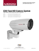
Installation and Operation Instructions Before attempting to connect or operate this product, please read these instructions completely. EXO Fixed HD Camera System High Definition Camera Systems for Harsh Environments EXVF5C-1...................720P, 12x optical zoom, Vandal resistant with wall / pole mount EXPF5C-1...................720P, 12x optical zoom, Pressurized with wall / pole mount EXVF5C-2...................1080P, 10x optical zoom, Vandal resistant with wall / pole mount EXPF5C-2................
IMPORTANT SAFEGUARDS 1 Read these instructions. 2 Keep these instructions. 3 Heed all warnings 4 Follow all instructions. 5 Do not use this apparatus near water. 6 Clean only with damp cloth. 7 CAUTION RISK OF ELECTRIC SHOCK DO NOT OPEN Do not block any of the ventilation openings. Install in accordance with the manufacturers instructions. 8 9 SAFETY PRECAUTIONS Cable Runs- All cable runs must be within permissible distance.
Product Warranty Registration Register Your Products Online www.moogS3.com/technical-support/product-registration Moog values your patronage. We are solely committed to providing you with the highest quality products and superior customer service. With 3-Year and 5-Year warranties (depending on the product purchased) we stand behind every product we sell. See full warranty details at www.moogS3.
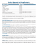
Limited Warranty for Moog Products Moog - Decatur Operations, subsequently referred to as “Manufacturer,” warrants these products to be free from defects in material or workmanship as follows: PRODUCT CATEGORY PARTS \ LABOR All Enclosures and Electronics Five (5) Years Accessory Brackets Five (5) Years Controllers Three (3) Years Power Supplies / IR Illuminators Three (3) Years Poles / PolEvators / CamEvator Three (3) Years Warrior Series™ / Q-View™ Three (3) Years SView Series Three (3) Yea
! English Electrical Specifications EXO Fixed Power Input: - 24VAC model - PoE 30W max. (with heater) IEEE 802.3-AT - 12VDC model 18W max. (with heater) Entrada de energía: - 24VAC modelos 30W max. (con calefacción) - PoE IEEE 802.3-AT Español - 12VDC modelos 18W max. (con calentador) Entrada de energía: - 24VAC modèles 30W max. (con calefacción) - PoE IEEE 802.3-AT - 12VDC modèles 18W max. (con calentador) Entrada de energía: - 24VAC Modelle 30W max. (con calefacción) - PoE IEEE 802.
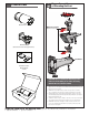
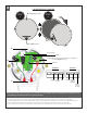
Contents of Box ! Proper Assembly of Mounting Bracket EXO Fixed Main Camera Wiring Access Holes: Must be rear facing Wall Mount (mount varies based on application) Base Mount Hardware Packet: Mount Gasket Screws CAUTION: When assembling the mounting bracket, make sure all the wiring access holes are facing towards the rear of the base mount.
WALL MOUNTING 1 2 If running wire through a conduit to the housing mount, first install appropriate fittings to the mount base. Attach mount to wall with suitable hardware (not provided). • Si se ejecuta a través de un cable de conducto a la carcasa de montaje, primero instale los accesorios adecuados para la base de montaje. • Si vous utilisez le câble dans un conduit à la monture logement, installez d'abord raccords appropriés à la base de monture.
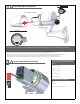
Pole or Wall Mount (Use Steel Straps to Mount to Pole) 5 6 Gasket Nipples Crimp Cable Ties Cable Cable Pierce the gasket nipples (as needed). Place the gasket as shown. Pass wires without connectors thru gasket and nipples. Crimp the connectors as needed. Then use cable ties on the nipples to secure, leave an extra 2” of cable. • Alimente el cable a través del soporte, perfore las entrerroscas de la junta (según lo necesitado). Coloque la junta como se muestra.
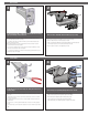
8 FACING REAR OF CAMERA STEP 1 (B- Completely loosen) STEP 2 (A- Slightly loosen) (B) RJ45 / PoE Input DETAIL M DATA DETAIL N Alarm IN 1 POWER *(Shipped from factory for 24Vac input. For 12Vdc input; see 12Vdc ADDENDUM section) Alarm IN 2 Detail M (A) Speaker Audio Ground (+) Detail N* Mic Ground Negative DC (-) AC (NEU) Positive DC (+) AC (Live) Make all final connections in the rear cavity.
9A ! To Access the Micro SD Card Slot: Loosen (2) screws FIRST: MAKE SURE UNIT IS POWERED OFF COMPLETELY 5mm Allen Wrench USE FORCE TO SPERATE See DETAIL A ________DETAIL A___________ FACING REAR OF ENCLOSURE ALLEN WRENCH HOLE SLOTS Thoroughly loosen the (2) captive screws (shown in DETAIL A) with provided 5mm Allen Key (included) to remove the front part of the camera system.
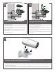
Pressurize the Unit (NOT required for the Non-Pressurized Vandal Unit) C 10 100 50 0 150 Air Chuck 200 250 PSI 300 Hose Regulator Nitrogen Tank When pressurizing unit be sure to set the gauge or regulator slightly above the housing pressure target of 5-7psi (0.35-0.5bar). Reinstall front of enclosure and tighten the (2) screws from step 9A. • Vuelva a instalar delante del gabinete y apriete los (2) tornillos del paso 9A. • Réinstaller l'avant de l'enceinte et serrer les vis (2) de l'étape 9A.
Depress the fill valve. Drain all air from the housing and repeat 3 times to remove all moisture. • Presione la válvula del terraplén. Salga todo el aire de la cubierta y de la repetición 3 veces de quitar toda la humedad. • Enfoncez la valve de suffisance. Évacuez tout l'air le logement et la répétition 3 fois d'enlever toute l'humidité. • Drücken Sie das Fülleventil nieder. Lassen Sie alle Luft aus dem Gehäuse und der Wiederholung 3mal, alle Feuchtigkeit zu entfernen ab.
14 If the pressure in housing is more than 5-7psi, drain the valve until you reach the specified level of 5-7psi. • Si la presión en la vivienda es más que el 5-7 psi, la válvula de desagüe hasta que llegue al nivel especificado de 5-7 psi. • Si la pression dans le logement est plus que 5-7 psi, vidanger le robinet jusqu'à ce que vous atteignez le niveau spécifié de 5-7 psi. • Wenn der Druck im Gehäuse ist mehr als 5-7psi, lassen Sie das Ventil, bis Sie die angegebene Höhe der 5-7psi erreichen.
12 VOLT DC AD D EN D U M PRODUCT SAFETY WARNING M oo g , I n c . R e c omme nds t he f o llo w ing ad d en d u m in stru ction b e d on e b y som eon e eq u i p p e d wi th t he c o r r e c t t o o ls a nd t ra ining. In a ddition to th ese in stru ction s, a workin g kn owledg e o f th e di s a sse m b l y / r e a sse mbly pro c e dure s is req u ired . If th e 12 volt DC in p u t settin g is n ot po s s i b l e a t y our f i e l d l o c a t io n, ple a se c o nt a c t Mo o g for fu rth er assistan ce.
A2 Remove the (2) side screws. These are located directly in front of the O-Ring gasket. • Quite los (2) tornillos laterales. Éstos están situados directamente enfrente de la junta tórica. • Retirez les (2) vis latérales. Ils sont situés directement en face de la joint O-Ring. • Entfernen Sie die (2) seitlichen Schrauben. Diese befinden sich direkt vor der O-Ring-Dichtung. • Rimuovere le (2) viti laterali. Questi si trovano direttamente di fronte alla guarnizione O-Ring. • Retire os (2) parafusos laterais.
A4 DISCONNECT ALL CONNECTORS (5) TOP VIEW - CABLE CONNECTION LAYOUT Disconnect all connectors. • Desconecte todos los conectores. • Débranchez tous les connecteurs. • Trennen Sie alle Anschlüsse. • Desligue todos os conectores. • Staccare tutti i connettori. A5 24v & PoE 12v Move all 3 jumpers to the right for 12V mode. Move jumpers to the correct position (as shown above). • Mueva los puentes en la posición correcta (como se muestra más arriba).
A6 CONNECT ALL CONNECTORS (5) TOP VIEW - CABLE CONNECTION LAYOUT Reconnect all connectors. • Vuelva a conectar todos los conectores. • Rebranchez tous les connecteurs. • Schließen Sie alle Anschlüsse. • Volte a ligar todos os conectores. • Ricollegare tutti i connettori. A7 PROPER CABLE MANAGEMENT Do not allow wires to interfere with fan. • No permita que los cables interfieran con ventilador. • Ne laissez pas les fils d'interférer avec ventilateur. • Lassen Sie keine Drähte mit Lüfter stören.
A8 While holding the camera bracket securely, reinstall the (2) camera bracket ring nuts. • Mientras sujeta el soporte de la cámara con seguridad, vuelva a instalar los dos (2) cámaras virolas soporte. • Tout en maintenant le support de la caméra en toute sécurité, réinstallez les deux (2) Support de caméra bagues. • Halten Sie die Kamera Halterung sicher, installieren Sie die (2) Kameraschiene Ringmuttern. • Enquanto segura o suporte da câmara de forma segura, reinstale os (2) Câmera suporte nozes anel.
A10 Reinstall front of enclosure and tighten the (2) screws from step 9A. • Vuelva a instalar delante del gabinete y apriete los (2) tornillos del paso 9A. • Réinstaller l'avant de l'enceinte et serrer les vis (2) de l'étape 9A. • Installieren Sie vor der Gehäuse und ziehen Sie die (2) Schrauben aus Schritt 9A. • Installieren Sie vor der Gehäuse und ziehen Sie die (2) Schrauben aus Schritt 9A. • Reinstallare Frontale della custodia e stringere le (2) viti dal passo 9A.
TABLE OF CONTENTS Software Sections Moog Discovery Tool ...................................................... ..................................................................................................... 1.0.0 Using the Moog EXO Web Application ............................. ..................................................................................................... 2.0.0 System Status ............................................................... .....................................
SOFTWARE SETUP 1.0.0 Moog Discovery Tool By factory default, the Moog EXO Camera is configured in DHCP. If you are not using a DHCP server it will automatically allocate itself an APIPA (Automatic Private IP Addressing) address in the range 169.254.0.1 to 169.254.255.254 with subnet mask 255.255.0.0. Initial device network configuration is done via the Moog Discovery Tool (MDT), a tool provided by Moog that can be found on the company’s web site and on the flash drive supplied with each camera system.
To configure the Unicast Discovery, add one or more IP address ranges. The Unicast Discovery tries to reach a device at a specific IP address in the configured ranges. The discovery can be a long process if the range of IP addresses is large and the device is at the end of the range. To accelerate the discovery, add several small ranges of IP addresses. The ping timeout option can be increased for a high latency network.
To assign IP Address, update firmware, or configure Moog web interface, right click on highlighted serial number / Mac Address. Assign IP Address(es) Once the IP information is set, the Silverlight web application served by the EXO Camera can be launched from the MDT or directly in your web browser by typing the device’s IP address in the address bar.
2.0.0 Using the Moog EXO Web Application Application When entering the Web Application, the following window will be displayed. You will be asked a username and password. The default User name and Password is ‘admin’.
2.1.0 System Status Status Window System Status - 2.1.0 Configuration - 2.2.0 Main Menu Tabs Maintenance - 3.0.0 Live Viewer - 4.0.0 Recording - 5.0.0 Upon successfully logging into the web interface, a welcome screen will be displayed. The welcome screen shows general device health status as well as firmware version and system uptime.
2.2.0 System Configuration Configuration / System Under the Configuration section, select the System tab to perform the following operations: • View product model information, current firmware version and serial number. • Specify a custom name; this name can be used by third-party software to display a selected name for the device. - Enable edge recording by checking the “Use Recorder Module” checkbox. Disabling edge recording will accelerate the device’s boot time.
2.2.1 Configuration / Date Time Under the Configuration section, select the Date Time tab to perform the following operations: • Set the time zone in which the device is operating. • Manually set the current date and time for the device’s internal clock. • Note: For an accurate time stamp, you must sync UTC Time. 2.2.
2.2.3 Configuration / Network / DHCP Under the Configuration section, select the Network tab to perform the following operations: • Set the camera’s IP parameters; DHCP or static IP information. • Configure an NTP server to allow the device to automatically update its internal clock using an NTP server. 2.2.
2.2.6 Configuration / Network / API- Boujour NOTE: • To control the EXO Camera system with a VMS software system, you must enable the required Network APIs. Enable PSIA or GENETEC API depending on which VMS platform you intend to use with the device. Disabling any unrequired APIs will accelerate boot time. • Note: ONVIF standard is built in and does not require activation. If using ONVIF you do not need to select an API. • Set Bonjour discovery protocol settings.
2.3.0 Configuration / Video In 2.3.1 Configuration / Video In / Video Input Under the Configuration section, select the Video In tab to perform the following operations: Digital format – choices are, 720 50fps, 720 60fps. 2.3.2 Configuration / Video In / Sensor Configure camera bloc / sensor parameters. These parameters will also be saved to the camera bloc itself if possible: Use the narrow pull down function for vertical and horizontal rotation of the image.
Configure video compression parameters for any of the three available codec instances (Primary H.264, Secondary H.264 and MJPEG). Most VMS software solutions will interact with these parameters and thus it is suggested to leave these at default values in the web interface. VBR aggressiveness however is unique to Moog EXO Cameras and proposes various levels (disabled to aggressive) of motion triggered rate control. The more aggressive the setting, the more variation motion will have on the rate control.
2.3.4 Configuration / Video In / Point to Point • Configure point to point video connections (up to three) for creating persistent video streams from the encoder to a network endpoint. 2.3.5 Configuration / Video In / Text Overlay Text Box To insert a text overlay: • There are (2) available strings (Text blocks). Select string. • Select string size. • For string position click mouse inside string position box. o Text bar will appear on video image.
2.3.6 Configuration / Video In / Motion Detection Select from 1 of 4 available regions: • With mouse click on region position box. • Bring mouse pointer to view window and drag box around area for motion detection. • Select desired Frame Count, Sensitivity and Thresholds. • Press “Save” button to store information. • You can select up to (4) separate “Motion” windows.
2.3.7 Configuration / Video In / Privacy Zones Privacy Zones are used to block out video in areas view is not permitted or desired. To add a Privacy Zone: • Select the Zone to be identified with privacy area. There are up to 16 zones available. • With the mouse, click on Privacy Zone Position Box. • Move mouse pointer over the Image Window, click and draw a box on the area you wish to see video. • Press the “Save” button to store.
2.3.8 Configuration / Audio In Under the Configuration section, select the Audio In tab to perform the following operations: • Configure audio input compression parameters. • Configure point to point audio connections (up to three) for creating persistent audio streams from the encoder to a network endpoint.
2.3.9 Configuration / Audio Out Under the Configuration section, select the Audio Out tab to perform the following operations: • Configure audio output parameters. • Configure a point to point audio connection for receiving a persistent audio stream from a network endpoint.
2.4.
Note: Recording Menu will NOT be visible unless activated; see 2.20 System configuration. • Grooming mode; Select method to remove files from full SD card. (Chronological will remove old files first.
2.4.1 Configuration / User Accounts Under the Configuration section, select the User Accounts tab to perform the following operations: • Select the web interface’s authentication method. A dual passphrase is made available for additional security. • Manage user accounts which have access to the device.
3.0.0 Maintenance This section describes how to update your Moog EXO Cameras to newer firmware versions from the web application. 1. To find the latest file go to http://videolarm.com/technical-support/software-firmware-downloads/. 2. Click on “EXO Camera Firmware” - click, save file. 3. Navigate to your device’s web application using your favorite web browser. 4. Click on the Maintenance tab. 5. Click on the Update button, locate downloaded firmware.
4.0.0 Live Viewer Use Live View for: • Live Camera View • Start and Stop Recording • Camera Control • Setting Presets • Adjust View Scale To enable live you must activate by pressing the “Play” button. Play Button To adjust viewing scale for 1024 x 768 monitor, press smaller view.
4.1.0 Live Viewer Pan / Tilt and Presets Lens Control Preset Controls • Speed Control: To increase speed, slide control knob to the right. • Lens Funtion: Use +/- buttons to update Iris, Zoom and Focus. • Preset Functions. • o First Select Preset Number. o Then position Camera and lens to desired position. o Press “Set” to save Preset. o For additional presets, repeat process. o To clear, select desired preset and press “clear”.
5.0.0 Recording To activate recording mode you must go to Configuration / System / Use Recorder Mode. Click “Use Recorder Mode” checkbox. This will activate addional Recording controls in the recording window. You must “Save” and then “Reboot” after making this change. > Select Video Input > Select Date of the Recording Then select the filed clip you wish to view Note: You must have either VLC Player or Windows Media Player installed.
6.0.0 Performing Batch Firmware Update This section describes how to perform a batch update of multiple Moog EXO Camera devices to newer firmware versions from the MDT. The batch firmware update works by starting a firmware update session. Only one session at time is allowed and only 20 devices can be selected by session. From the MDT, select one or more devices of the same type. By using the right mouse button on the selected devices, choose the “Firmware Update” menu option.
To start a firmware update session, choose the “.iof” file corresponding to the new firmware by clicking to the “Select File …” button. Once selected, click the “Start” button. 75% Once started, the “Firmware Update Session” window shows the progress of the firmware update. This window can be closed at any moment without losing the current session.
If closed, the progress of the current session can be followed by reopening the “Firmware Update Session” window by clicking the from the “Tools” toolbar. button Once done, clear the current session from the “Firmware Update Session” window and restart a new session if needed. 7.0.0 Point to Point Connections Point-to-point connections between a Moog EXO Camera and a Decoder can be configured using the device’s web application.