Understanding and Using Your moogerfooger® MF-105M MIDI MuRF® TABLE OF CONTENTS Getting Started............................................3 Frequencies and Filters...............................5 The MIDI MuRF’s Filters...........................7 Envelope Generators.................................10 Sequencers and Pattern Generation..........10 The MIDI MuRF’s Animation..................11 The MIDI MuRF’s Tap/Step Input..........13 Audio Level Controls and Mixing............
Welcome to the world of moogerfooger® Analog Effects Modules! Your model MF-105M MIDI MuRF is a rugged, professional-quality instrument, designed to be equally at home on stage or in the studio. Its great sound and jaw-dropping effects come from state-of-the-art analog circuitry, designed and built by the team at Moog Music in Asheville, North Carolina. The MF-105M is full of the very same analog goodness that Bob Moog designed into the original award-winning MF-105 MuRF and the MF-105B Bass MuRF.
GETTING STARTED Here are some simple instructions on how to plug in and try out your MF-105M before you have read through the entire manual. 1. Unpack your MF-105M. Place it on a table while you become familiar with its controls and connections. Gently pat the wooden side pieces of your new moogerfooger to let it know that it has found its new home and that it will be well cared for. 2.
5. Connect a MIDI Cable from the MF-105M’s MIDI In to the MIDI Out on a MIDI Controller of your choice: MIDI sequencer, Drum Machine, a MIDI foot controller like the MP-201 Multi-pedal, or a MIDI keyboard. The MIDI MURF defaults to MIDI Channel One so make sure that the MIDI controller is transmitting on MIDI Channel 1. Be sure to check out the MIDI MuRF Controller and Pattern Editor application available from www.moogmusic.com. 6. Connect an instrument cable from your signal source to the AUDIO IN jack.
automatically in sequence by the Animation at a tempo determined by the RATE control. Note that changing the ENVELOPE control affects the shape that turns the filters up and down. The PATTERN rotary switch selects different patterns that dictate the sequence that turns the Filters up and down automatically. The MIX control is used to blend the direct sound of your instrument with the effected sound. 8. If your MIDI controller can send MIDI Clock Messages, start sending them.
In general, bright sounds have lots of strong overtones, while darker, mellower sounds have fewer (and weaker) overtones. A filter is a signal-modifying device that colors a sound by emphasizing some parts of the audio spectrum and attenuating (cutting down) other parts. In general, a filter has a quality of its own which is superimposed on the tone color of the original sound. Some types of filters (like the bass and treble controls on your sound system) have subtle, gentle effects on a sound’s timbre.
The MIDI MuRF’s FILTERS The MIDI MuRF contains 8 filters that can be configured for bass or mid-frequency voicing by the FREQ slide switch on the front panel. In the BASS voicing, the lowest filter acts as a lowpass filter with a cutoff frequency of 110 Hz. This is ideal for bass players or bass sounds that need to retain the presence of all their lowest frequencies. The remaining seven filters are resonant filters with center frequencies of 160, 240, 350, 525, 775, 1200 and 1800 Hz.
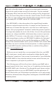
can hear the effect of just the filters. 3) Make sure the effect is on, and MIX is at 10. Figure 5 - Testing the Filters 4) Connect just the "left/mono" output to your amplification. You may want to experiment with the panel controls and switches as we discuss each of the parameters.
Figure 7 - BASS Frequency Response 7) The Filters’ resonant frequencies can be shifted up and down by a small amount to create an effect similar to phasing. Figure 8 shows a graph that portrays the results of shifting a resonant filter’s center frequency. In the MIDI MuRF this can be done two ways, depending on the position of the LFO slider switch.
ENVELOPE GENERATORS Now that we have explained the MIDI MuRF’s filters, let’s proceed with some more definitions to explain the Animation function. The term "Envelope" is used to describe the changes that occur to a musical sound, from its start to its end. A musical sound can have a rapid onset, like the plucking of a string or the striking of a drum. It can also have a gradual onset, like a slowly bowed violin. With the term "Envelope", the shape of the start of a sound is called the "Attack".
well. Vintage sequencers were typically designed so there were a certain number of "steps". The term "step" refers to the individual components of a pattern. For instance in a bar of music in 4/4 you have four quarter notes. If the rhythmic activity is no more complicated than quarter notes, this would correspond to four steps. In vintage analog sequencers, a sequencer typically had eight or sixteen steps available to build a pattern.
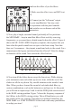
Figure 10 - MIDS Pattern 2 individual filters. Illustrations of all the Patterns are in Appendix A, page 27. Return to the basic setting shown in figure 2, which features pattern 2. As you play your instrument through the MIDI MuRF, pay attention to the sound of the effect and how it corresponds to figure 10. You should hear the Animation "stair-stepping" through the filters. Turn the RATE control up and down and notice how the pattern speeds up and slows down.
11 shows the changes to the envelope times at different settings of the Envelope control. The Envelope times also change as the RATE Figure 11 - Envelope shape morphing with changes. Faster Rate settings the ENVELOPE control decrease the envelope times and slower Rate settings increase the envelope times. This makes the MIDI MuRF capable of both rhythmic and smooth-changing, swirling effects.
THE AUDIO LEVEL CONTROLS AND MIXING The DRIVE control adjusts the signal level at the MIDI MuRF’s circuit input. With this control you can set the right input level for virtually any instrument or line-level signal source. Turn this control counterclockwise for strong input signals, and clockwise for weaker sound sources. The DRIVE light tells how strong the input signal is after being adjusted by the DRIVE control.
of the left and right outputs when both the left and right output jacks are used. Note that the odd-numbered filters are sent to the left channel, and the even-numbered filters are sent to the right channel. This allows for spreading a sound’s frequencies between two speakers. Figure 12 - Left and Right Frequency Response of MIDS filters EXPRESSION PEDALS AND VOLTAGE CONTROL You now know what each of the rotary controls does to the sound of the MF-105M.
position increases that value, pulling back to heel position decreases the value. The expression pedal inputs can also be used as control signal inputs. This enables you to use your MF-105M with virtually any control signal source: modular analog synthesizers, MIDI-to-CV converters, etc. You will find information on interfacing your MF-105M with external control signal sources in the Technical Information section on page 23.
setting, and 13-24 are accessed by the PATTERN switch in the MIDS voicing setting. Using MIDI Program Change Messages values 0-23 accesses the MuRF patterns 1-24. This has no impact on the position of the FREQ switch, so that using MIDI, you can use any of the 24 patterns with either voicing, overriding the front panel PATTERN and FREQ switch positions. Moving the PATTERN rotary switch or the FREQ switch restores the MIDI MuRF to the state of those front panel controls.
MIX: CC8. When the MF-105M receives a CC8 message on the MIDI channel that is assigned, the value of the CC8 message overrides the setting of the front panel MIX control and any steady voltage at the MIX control input. Moving the front panel MIX control or modifying a voltage at the MIX control input restores this parameter to its front panel state.
setting (i.e. the switch in the ON position, and the MIDI CC85 value received is 0). Moving the front panel LFO switch restores this parameter to its front panel state. FREQ BASS/MIDS: CC86; Values 0-63=BASS; 64-127=MIDS. When the MF-105M receives a CC86 message on the MIDI channel that is assigned, the value of the CC86 message overrides the setting of the front panel FREQ switch if it is in the range of values that is opposite the current setting (i.e.
clock and returns the MIDI MuRF’s filters to control by the EGRs triggered by the current Pattern. If the Pattern selected has no Animation (i.e. factory default pattern 1) then upon receiving one of these CC messages, the corresponding filter level is set by that CC value, while all other filter levels are set to ON (before the sliders). If the pattern selected has Animation (i.e.
1/8 note (CC Values 084-089), Clock messages: 12 Dotted 1/16 (CC Values 090-096), Clock messages: 9 1/16 note (CC Values 097-102), Clock messages: 6 Dotted 1/32 (CC Values 103-108), Clock messages: 4 1/32 note(CC Values 109-115), Clock messages: 3 Dotted 1/64 (CC Values 116-121), Clock messages: 2 1/64 note (CC Values 122-127), Clock messages: 1 A MIDI Clock Stop Message will stop the Pattern’s playback until a MIDI Clock start message is received, a MIDI Clock Continue message is received or until the Fron
that is assigned, the MIDI MuRF pattern clock stops running, and that filter’s EGR is fired. If a Note On is held until the EGR goes through its complete attack/decay cycle, a new Note On message is required to retrigger the EGR. An EGR is retriggered from the last point in the EGR cycle if retriggered before the Decay segment reaches the end of its cycle. This is an "8-voice polyphonic" mode – so up to all 8 filters can be fired at once (in the order they are received serially).
Mute Mode cannot be used at the same time as Step Mode so if Note on Value 108 is received, Mute Mode Note on values are ignored. MIDI CCs 20-27 are treated with priority over the Note On Modes to control the levels of Filters 1-8. PATTERN CLOCK RESET: If the pattern clock is stopped due to a MIDI Note mode or MIDI C20-27, MIDI Note 65 (F above Middle C) will re-start the pattern animation. If the pattern clock is running, MIDI Note 65 will re-set the pattern to step 1.
SOME TYPICAL SETUPS UPWARD STAIRCASE WITH RHYTHMIC VARIATION Here is a variation on the basic setting of figure 2 that shows off the ability of the MuRF to create rhythmic variations within the patterns. This is really nice with sustained chords or slowly arpeggiated playing. SWIRLING CASCADES This setup shows off the long envelope times of the MuRF, creating a shimmering, slowly evolving timbral landscape for your playing.
TECHNICAL INFORMATION NOTE: The following information is intended for use by people who understand analog electronic circuitry and have enough practical experience to interconnect sophisticated electronic equipment correctly. FIRMWARE UPDATE VIA MIDI: The MF-105M can be enabled to receive MIDI SysEx data containing the Operating Firmware for the MIDI MuRF by powering up in what is called "Bootloader Mode".
PEDAL INPUTS: All pedal control input jacks are 1/4" tipring-sleeve (stereo) phone jacks. The sleeves are grounded and the ring terminals are supplied with +5 volts which is current-limited. The tip terminals receive the variable voltages from the pedals. An expression pedal for use with the MF-105M should contain a 50KOhm or 100KOhm linear taper potentiometer which is connected from the sleeve to the ring terminals.
voltages to the tips of the pedal control input jacks. The LFO/SWEEP jack can also receive 0 to +5 Volt programming voltages. AUDIO PATH: The bypassed signal goes to the LEFT/ MONO output jack. Thus, when the MIDI MuRF is bypassed, the signal at the LEFT/ MONO output jack is the same as what your instrument is producing, and there is no signal at the right output jack. The MF-105 will not pass an audio signal unless power is applied to it.
APPENDIX A: THE MuRF’s PATTERNS BASS FILTER VOICING 1) No Animation 2) Downward Staircase 3) Upward Cascade 4) DoubleX 5) Perpetual Motion 6) Stereo Pyramid page 28
7) Double Dip 8) Inverted Rhythmicon 9) Prime Number Rhythmicon 10) Folded Rhythmicon 11) Breakbeat 12) Big Beat page 29
MIDS FILTER VOICING 1) No Animation 2) Upward Staircase 3) Downward Cascade 4) Criss Cross 5) Brownian Motion 6) Random-like page 30
7) Downward Band Expansion 8) Down and Up 9) Pulsar 10) Growing and Shrinking Band 11) Double Cascade 12) Rhythmicon page 31
APPENDIX B: MIDI Implementation Chart MF-105M MIDI MuRF MIDI Implementation Chart Date: 08/24/09 version: 1.
APPENDIX C: WARRANTY INFORMATION LIMITED WARRANTY Moog Music warrants that its products will be free from defects in materials or workmanship, and shall conform to specifications current at the time of shipment, for a period of one year from date of purchase. During the one-year period, any defective products will be repaired or replaced, at Moog Music’s option, on a return-to-factory basis. This Warranty covers defects that Moog Music determines are no fault of the user.
Appendix D: MF-105M SPECIFICATIONS DESCRIPTION: Analog effects module incorporating two functions: 8 – band Resonant Filter Bank and 24-Pattern Sequencer triggering Volume Envelopes for 8 Filters with CV and MIDI control. FRONT PANEL FEATURES: DRIVE rotary control - adjusts the gain of the audio input to the effect. OUTPUT rotary control - balances the level of MuRF’s signal when the effect is on with the bypassed signal when the effect is off.
RATE, ENV, LFO/SWEEP, MIX, all of which are TRS 1⁄4" jacks that accept moogerfooger EP1 (or equivalent) expression pedals, or control voltages from two-circuit or three-circuit 1⁄4" jacks. TAP/STEP IN 1⁄4" TRS phone jack – provides a means of syncing the tempo of the MuRF’s Animation Patterns to the tempo of the music by tapping an external footswitch (Moog FS-1, or equivalent) three times.