Understanding and Using Your moogerfooger® CP-251 Control Processor Moog Music Inc. Asheville, NC USA ©2000, 2003 by Moog Music Inc.
Welcome to the world of moogerfooger® Analog Effects Modules! Your Model CP251 Control Processor is a rugged, professional-quality instrument, designed to be equally at home on stage or in the studio. Its great functionality and classic effects come from its state-of-the-art all-analog circuitry, designed and built under Bob Moog's personal direction. Your CP251 is a direct descendent of the original modular Moog™ synthesizers.
SOME BASIC THEORY When you first try out an audio processor like a ring modulator or phaser, you plug your instrument into the AUDIO IN jack, connect the AUDIO OUT jack to your amplifier, and immediately hear what it does by playing your instrument. There are no AUDIO IN or AUDIO OUT jacks on the CP251. This is because it is not designed to process audio (musical sounds).
control input jack to change the oscillator's frequency, or you can use both together. We call this kind of oscillator a voltage-controlled oscillator (VCO). The voltage applied to the frequency control input is called (you guessed it) the frequency control voltage or, since the pitch that we hear is directly related to the frequency of the oscillator's signal, the pitch control voltage.
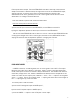
applied to the VCO's pitch control input. The mixer in Figure 3 contains a circle with a "+" in it. This is a way of showing that the two input signals are combined, or added together. The player adjusts the LFO Frequency (sometimes called Rate) knob to change the vibrato rate, the Mixer Input Level control to change the amount of vibrato, and the VCO Frequency control to transpose the pitch range of the keyboard. Figure 3 - Using a mixer circuit to combine LFO and KEYBOARD control signals.
GETTING STARTED We are about to embark on a tour of your CP251's functions. To do this, you'll need the following items: • Your CP251, • A tone generator of some sort, whose frequency is voltage-controlled, • An expression pedal such as the moogerfooger EP-1, • Six or eight short (1’-3’) patch cords with ¼” phone plugs, • A monitor amplifier-speaker. We’ll feed the CP251’s signals into the tone generator’s frequency control input, and then listen to how the generator’s pitch changes.
receptacle. (See Page 28 for more detailed information on power adapters for the CP251.) Note that the LED in the LFO section lights up. Before we begin on our tour, let's look at two of the CP251's features. Placing your CP-251: Unlike the moogerfooger MF-Series effects modules, the CP251 is housed in a low rectangular enclosure. It's designed to be used in conjunction with one or more MFSeries modules and/or other voltage-controlled gear, and to be placed where it is most convenient.
octaves. Turn the RATE knob slowly to hear the LFO's full speed range. •Turn the RATE knob counterclockwise. •Plug an expression pedal into the PEDAL IN jack. Vary the setting of the pedal to hear its effect on the LFO speed. Figure 4 - Setup for trying out the LFO module. ATTENUATORS An ATTENUATOR cuts down the strength of a signal. Your CP251 has two identical attenuators, each of which has an input jack, an output jack, and a knob.
LFO's square wave output. Turn the ATTENUATOR knob back and forth. Note that the shape of the effect is determined by the signal that is fed to the ATTENUATOR's input, and the amount or intensity of the effect is determined by the setting of the ATTENUATOR knob. This is generally true for all control signal sources and all control destinations on voltage-controlled devices. Now we'll illustrate a patch that uses both attenuators.
• Set knobs as follows: a) All four MIXER knobs to midposition, b) LFO RATE to 9 o'clock. A mixture of triangular and square waveforms will be modulating your tone generator. Vary the setting of the "1" knob to change the strength of the triangular wave, the "2" knob to change the strength of the square wave, the OFFSET knob to raise and lower the waveforms, and the MASTER knob to change the amplitude of the entire mix. Plug your expression pedal into input 3.
c) from the ATTENUATOR OUT jack to your VCTG pitch control input. • Set knobs as follows: a) both RISE and FALL fully counterclockwise, b) ATTENUATOR knob to midposition, c) RATE to 9 o'clock. Note that the waveform sounds perfectly square. Now turn the RISE knob slowly clockwise. Note that the rising portion of the square wave is being slowed down. Next turn the RISE knob back to full counterclockwise and the FALL knob slowly clockwise. Note that the falling portion of the square wave is being slowed down.
a) from one of the unused MULTIPLE jacks, to the IN jack of an ATTENUATOR, b) from the ATTENUATOR OUT jack, to the PEDAL IN jack of the LFO. These connections enable the expression pedal to control the LFO rate. The rate range is determined by the setting of the attenuator knob. • Connect more patch cords as follows: a) from an unused MULTIPLE jack to INPUT 1 of the MIXER, b) from the LFO TRIANGULAR output to INPUT 2 of the MIXER, c) from the MIXER "+" output to your VCTG pitch control input.
NOISE SOURCE The NOISE SOURCE has a single output jack. It delivers a waveform that is completely random. When you listen to this waveform directly, you will hear a steady pitchless "white noise" sound. When you apply the waveform as a control voltage, you will hear the resultant sound become rough and "static-y". Temporarily connect the NOISE jack directly to the input of your audio monitor. Note the distinctive "white noise" quality of the waveform.
the LFO rate, so turning the LFO RATE knob affects how smooth the OUT 2 waveform is. When no patch cord is plugged into the IN jack, the NOISE waveform is bridged to this jack. When no patch cord is plugged into the TRIG jack, the LFO square waveform is bridged to this jack. • Connect patch cords as follows: a) from OUT 1 to an ATTENUATOR IN jack, b) from the ATTENUATOR OUT jack to your VCTG pitch control input. Note that the pitch is changing in random steps at the LFO rate.
USING THE CP-251 WITH OTHER MOOGERFOOGER MODULES The following examples show a few ways that you can use your CP251 with other moogerfooger modules. With each example that you try, be sure to experiment with the settings of all the knobs that you are using. Understand what each knob controls, and what function each patch cord performs. Try out your own variations. You will be delighted at the range of effects that you will discover.
BASIC SETUP: RANDOM STEP FILTER • Connect patch cords as follows: a) Expression Pedal to CP251 LFO PEDAL IN jack. b) CP251 S+H OUTPUT 1 jack to MF101 CUTOFF jack. • Set knobs as follows: a) MF101: AMOUNT “ 0” ; MIX “ 10” ; CUTOFF midposition; RESONANCE “ 7” . b) CP251 LFO RATE at about 10 Hz (1 o’clock). Play sustained tones through the MF101. (Brighter tones yield more audible filter effects.) Note the random filter effect.
Play a staccato line. The filter cutoff will change after every note that you play, so each note has a different tone color. However, the cutoff glides from one frequency to the next because of the smoothing action that is associated with S+H OUT 2. Note that the LFO RATE sets the speed of the glide.
that the rise of the modulation waveform is much faster than the falling part. Now change to RISE knob to “ 7” and the FALL knob to “ 0” to produce a modulation waveform in which the falling part is much faster than the rising part. Experiment with the LAG knobs, the ATTENUATOR knob, and the MF101 CUTOFF and RESONANCE knobs to explore the different effects that can be achieved by “ playing” the knobs that affect the modulation waveform. Figure 12 - Setup for LFO modulation examples.
Talking Bass” (A patch that uses both an MF101 Lowpass Filter and an MF102 Ring Modulator) Figure 13 - Setup for “ Talking Bass” .
b) Output of your instrument to MF101 AUDIO IN, c) MF102 AUDIO OUT to input of your monitor amp, d) Expression Pedal to CP251 LFO PEDAL IN jack, e) CP251 LFO Square Wave out jack to LAG IN jack, f) CP251 LAG OUT jack to ATTENUATOR IN jack, g) ATTENUATOR OUT jack to MF101 CUTOFF jack.
Turn down the monitor amp to a comfortable level. You’ll hear frequency modulation of the carrier oscillator by the two LFO waveforms. MIXER IN 1 and IN 2 determine the strengths of the individual LFO waveforms, MASTER sets the overall strength of the dual LFO waveform, and OFFSET raises and lowers the voltage at the center of the dual LFO waveform, thereby raising and lowering the pitch of the carrier oscillator.
“ Phaser-rhythm” This patch uses the voltage steps at the CP251 S+H OUT 1 jack as the audio input to an MF103 12-Stage Phaser. The sharp voltage rise at the beginning of each step creates a wideband click. This causes the phaser to “ ring” simultaneously at several frequencies, thereby converting the click into a distinctive percussive tone. Figure 15 - Setup for “ Phaser-rhythm” .
b) CP251 S+H OUT 1 jack to MF103 AUDIO IN jack, c) MF103 AUDIO OUT jack to Monitor Amp. • Set Knobs and Switches as follows: a) CP251: LFO RATE to 1 o’clock, b) MF103: AMOUNT “ 0” ; RATE SWITCH “ HI” ; RATE “ 3” (8:30); DRIVE 9 o’clock (so LEVEL light blinks green and yellow); OUTPUT LEVEL 3 o’clock; SWEEP midposition (“ 5” ), MODE switch on “ 12-STAGE” ; RESONANCE “ 10” . You will hear a repeating series of pitched pulses. Each step at the S+H OUT 1 jack creates one pulse. The pulses vary in loudness.
TECHNICAL INFORMATION This section contains technically-oriented information which is somewhat more detailed than the previous sections . Some users will find this information helpful in devising advanced uses for the CP251. The information is arranged according to the CP251 module to which it applies. MIXER The nominal input resistance of inputs #1 and #2 is 50KW. The nominal input resistance of inputs #3 and #4 is 100KW. The nominal output (source) resistance of each of the outputs is 500 W.
maximum frequency is greater than 100 Hz. The nominal peak voltage of the triangular and square waveforms is ±2.5 volts . The nominal output (source) resistance of each of these outputs is 500 W. ATTENUATORS Each of the attenuators is a 50KW, linear taper potentiometer. The IN jack is connected across the potentiometer element, while the OUT jack is connected from the counterclockwise end of the element, to the potentiometer’s wiper arm.
novel control devices that are powered by the CP251’s red jacks (as well as by any of the pedal/control jacks on moogerfooger MF-Series products). Plugging a conventional two-circuit phone plug (tip-sleeve) into any of the red jacks will not adversely affect the operation of any part of the CP251. Such a phone plug will short that jack’s pedal supply to ground, causing a current of about 2 milliamperes to flow through the plug’s barrel.
LIMITED WARRANTY Moog Music warrants that its products will be free from defects in materials or workmanship, and shall conform to specifications current at the time of shipment, for a period of one year from date of purchase. During the one-year period, any defective products will be repaired or replaced, at Moog Music's option, on a return-to-factory basis. This Warranty covers defects that Moog Music determines are no fault of the user.