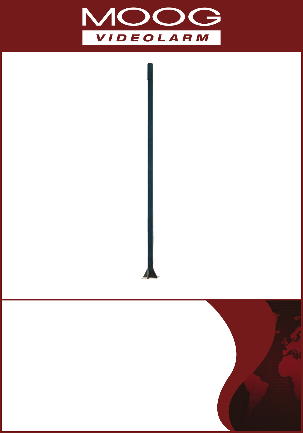
© 2011, Moog Videolarm, Inc. All Rights Reserved P1600 CCTV Standard Steel Pole www.videolarm.com Installation and Operation Instructions for the following model: P1600 Standard 16’ Steel Pole Before attempting to connect or operate this product, please read these instructions completely.
IMPORTANT SAFEGUARDS 1 Read these instructions. 2 Keep these instructions. 3 Heed all warnings 4 Follow all instructions. 5 Do not use this apparatus near water. 6 Clean only with damp cloth. 7 CAUTION RISK OF ELECTRIC SHOCK DO NOT OPEN Do not block any of the ventilation openings. Install in accordance with the manufacturers instructions. 8 9 SAFETY PRECAUTIONS Cable Runs- All cable runs must be within permissible distance.
Limited Warranty for Moog Videolarm Products Moog Videolarm warrants these products to be free from defects in material or workmanship as follows: PRODUCT CATEGORY PARTS \ LABOR All Enclosures and Electronics* Five Poles/PolEvators™/CamEvator Three (3) Years Warrior Series™/Q-View™/IR Illuminators Five (5) Years SView Series™ Five (5) Years **6 months if used in auto scan/tour operation Controllers Five (5) Years Power Supplies Five (5) Years EcoKit Three (3) Years Accessory Brackets F
1 2 Part 1: Site Preparation Figure 1 ! NOTE: Part 1: Site Preparation 1. Select a suitable site for the P1600 and prepare the pad site using a hole 36" x 36" x 36" deep. The top of the concrete Special attention must be paid to the size of the wiring conduit and its location within the foundation should be flush with the ground. concrete foundation and jig (if applicable.) The Wiring Conduit can be up to 2" in ! diameter. Use reducers if necessary.
4 3. 5 Part 1: Site Preparation Figure 3 FOR ANCHOR BOLT INSTALLATIONS: Part 1: Site Preparation Figure 4 ! Pour concrete per manufacrurer’s directions. See Figure 3 for dimensions of the bolt pattern and suspend appropriate bolts in the concrete around the wiring conduit. Leave 2” to 3” of the BOLTS protruding above the pad. If you are using leveling nuts, leave 4” to 6” protruding. Prepare the concrete per manufacturer's directions.
8 9 Part 2: Installation Figure 7 Part 2: Installation Figure 8 5. Slowly lift the pole into the upright position, aligning the holes of the Base Plate with the Bolts in the concrete pad (Figure 7). 6. Secure the pole to the pad with fasteners (Figure 8). Nut CAUTION: Pull all slack in the wiring as you lift the pole into position Lock Washer to keep from pinching and possible damage. Flat Washer 5. Ensure that the pole is vertical on all sides. Use a bubble level or plumb bob to check.
12 Jig Assembly Figure 2 2. Place the short end of each Bolt into the outside holes of the Cross Strap. Place Hex Nuts onto each Bolt and finger tighten (Figure 2). 14 7 Jig Assembly Figure 4 25 13 Jig Assembly Figure 3 3. Turn the Anchor Jig over and place Single Straps over the Bolts (Figure 3). Use the inside hole of each strap. Place Hex Nuts onto each Bolt and finger tighten. 15 Jig Assembly Figure 5 / 32 " 11" diameter 7 / " 25 32 4.
16 Jig Assembly Figure 6 17 Jig Assembly Figure 7 With Leveling Nuts 6. If, due to conditions or other requirements, leveling nuts are needed, adjustments will have to be made to the Anchor Jig . Leveling nuts and washers are NOT provided with the pole, NOTE: The Flat Washers, Lock Washers , and remaining Hex Nuts will be used to fasten the pole to the Anchor Jig.
Product Registration/Warranty Thank you for choosing Moog Videolarm. We value your patronage and are solely committed to providing you with the highest quality products available and superior customer service. Should a problem arise, rest assure that Moog Videolarm stands behind its products by offering impressive warranty plans: 3 Years on all Housings, Poles, Power Supplies, and Accessories and 5 Years on camera systems (SView, QView, Warriors), and InfraRed Illuminators.