© 2011, Moog Videolarm, Inc. All Rights Reserved PB24L900 Rugged Wireless Power Box www.videolarm.com Installation and Operation Instructions for the following model: PB24L900 A rugged outdoor wireless box, with a 220/110Vac input and 24Vac output for camera, fuse protected. With a wireless 900MHz transmitter and matching receiver. Omni directional antenna. Before attempting to connect or operate this product, please read these instructions completely.
IMPORTANT SAFEGUARDS 1 Read these instructions. 2 Keep these instructions. 3 Heed all warnings 4 Follow all instructions. 5 Do not use this apparatus near water. 6 Clean only with damp cloth. 7 CAUTION RISK OF ELECTRIC SHOCK DO NOT OPEN Do not block any of the ventilation openings. Install in accordance with the manufacturers instructions. 8 9 SAFETY PRECAUTIONS Cable Runs- All cable runs must be within permissible distance.
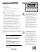
Limited Warranty for Moog Videolarm Products Moog Videolarm warrants these products to be free from defects in material or workmanship as follows: PRODUCT CATEGORY PARTS \ LABOR All Enclosures and Electronics* Five Poles/PolEvators™/CamEvator Three (3) Years Warrior Series™/Q-View™/IR Illuminators Five (5) Years SView Series™ Five (5) Years **6 months if used in auto scan/tour operation Controllers Five (5) Years Power Supplies Five (5) Years EcoKit Three (3) Years Accessory Brackets F
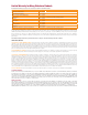
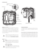
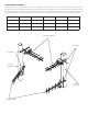
PB24L900 Power Box Wall Mounting: A template is provided in the back of the instruction with the 2 x 8 bolt DESCRIPTION pattern required for the mounting of this product. Hardware is not provided PB24L900 is an 84vA Power Supply, designed for either 230Vac or for mounting this unit to the wall. 115vac input with 24Vac output. The unit includes a 900MHz wireless transmitter and matching receiver with an omni-directional antenna.
Connecting Power: 24VAC Power to Housing (Detail) H&B H&B Camera Camera Ground Post Incoming Ground 24VAC Power to Housing A 24VAC Optional Output 120VAC Input GROUND 220-240VAC Input CONNECTING POWER Main On/Off Switch Input: (120Vac or 240Vac) The Power Box provides 2 separate power output(s) at 24V. The Power Box is designed for either 120 or 240Vac input single phase. A single (3) position connector is provided with each unit.
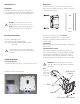
WIRELESS SETUP LED Name Function Color Once the dome is installed and power is connected to it, the wireless master 1 Power Unit has power and has successfully booted. Red unit must be installed. Below is the basic setup for the master RF unit. Please 2 RF Link The radio has successfully linked with its partner. Green 3 RF TX Radio transmission is occurring. Green 4 RF RX Radio reception is occurring.
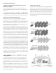
INSTALLATION: should never try to point the ends of the antenna directly toward one another or directly Once you have installed the antennas on the dome and master unit. You need to aim away from one another. The 11dbi antennas are directional. They are designed so the antennas so they are aligned with each other and they both have the same polarity. If the radio wave will project directly out the front of the antenna.
INSTALLING MULTIPLE ANTENNAS: When installing more than one wireless unit in the same location, it is important to make sure that great care is taken to insure that the radio frequencies (channels) are properly spaced apart. For tower applications with two or three wireless master units in close proximity on the same pole, Videolarm recommends utilizing the manual channel mode; antenna gain of 11dBi and mixed polarization between antennas.
Up to 12 Radios – Advanced tower installations with many pan and tilt units will require careful planning and assessment by a qualified radio technician. Videolarm recommends utilizing the manual channel mode; antennae gain of 11dBi and mixed polarization between channels. It is recommended that antennae maintain a minimum of 4 ft of physical separation and are oriented with greater than 45° of angular separation.
FAQ (Frequently Asked Questions) 1. What is the maximum number of Ethernet devices that can transmit across the link? 7. What is the Fresnel zone? There is no limit to the number of client devices whose Ethernet traffic can be spread out into after they leave the antenna. Typically, 20% Fresnel Zone transported. The WIRELESS DOME supports an unlimited number of MAC addresses blockage introduces little signal loss to the link. Beyond 40% blockage, signal across the link. loss will become significant.
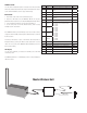
Exploded View for Replacement Parts 4 1 A 2 3 Replacement Parts List Part Number Description 1 RP40HGPB1000 PB24 Housing Assembly 2 RP40BRPBL24 900 MHz Bracket Assembly With Transformer and PCB 3 RPPB241000 Grounding Stud and Terminal Connector 4 RP70WPPH13 3 Position Incoming Power Plug Power Connection 120VAC ON 120 VAC Brown 220 VAC INPUT 115V 50/60hz Brn/Wht Black Green 24VAC at 3.
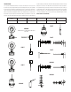
Exploded View for Replacement Parts 9 1 5 2 8 6 7 8 7 9 3 4 4 5 6 3 2 Replacement Parts List Part Number 1 RPVL2879 Wireless Base Bracket A 2 RP70TRANS11 96VA 220/110 TO 24 CE/UL TRANSFORMER 3 RPVL2885 Wireless box, bracket B 4 RP76PCBPB01 POWER BOX CONNECTION PCG 5 RP70WPPH08 3.
Mounting Template 8.00 [ 203.2 ] 2.00 [ 50.
Product Registration/Warranty Thank you for choosing Moog Videolarm. We value your patronage and are solely committed to providing you with the highest quality products available and superior customer service. Should a problem arise, rest assure that Moog Videolarm stands behind its products by offering impressive warranty plans: 3 Years on all Housings, Poles, Power Supplies, and Accessories and 5 Years on camera systems (SView, QView, Warriors), and InfraRed Illuminators.