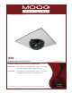
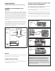
© 2011, Moog Videolarm, Inc. All Rights Reserved QOD Drop Ceiling Office Surveillance Housing www.videolarm.com Installation and Operation Instructions for the following models: QODT2-70NA Drop Ceiling indoor housing, tinted dome, replaces 2’ x 2’ ceiling tile, with (2) Day / Night cameras, 3-9mm auto-iris lens. QODT4-70NA Drop Ceiling indoor housing, tinted dome, replaces 2’ x 2’ ceiling tile, with (4) Day / Night cameras, 3-9mm auto-iris lens.
IMPORTANT SAFEGUARDS 1 Read these instructions. 2 Keep these instructions. 3 Heed all warnings 4 Follow all instructions. 5 Do not use this apparatus near water. 6 Clean only with damp cloth. 7 CAUTION RISK OF ELECTRIC SHOCK DO NOT OPEN Do not block any of the ventilation openings. Install in accordance with the manufacturers instructions. 8 9 SAFETY PRECAUTIONS Cable Runs- All cable runs must be within permissible distance.
Limited Warranty for Moog Videolarm Products Moog Videolarm warrants these products to be free from defects in material or workmanship as follows: PRODUCT CATEGORY PARTS \ LABOR All Enclosures and Electronics* Five Poles/PolEvators™/CamEvator Three (3) Years Warrior Series™/Q-View™/IR Illuminators Five (5) Years SView Series™ Five (5) Years **6 months if used in auto scan/tour operation Controllers Five (5) Years Power Supplies Five (5) Years EcoKit Three (3) Years Accessory Brackets F
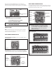
TABLE OF CONTENTS Cable and Power Guidelines Electrical Specifications General Instructions Wiring Camera Adjustment Camera Focusing Camera Settings Completion of Installation NVT Instructions Warranty Information Service and Safeguard Information Troubleshooting 1, 10 1 1 1 1 1 2 4 4 6 7 8 4. Align the eyelet on the cord with the hole located on the inside of the housing tile opening. 5. Insert the 6-32 x 1/2 round Phillips head screw through the hole and eyelet.
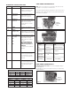
Vari-Focal Lens: First, adjust the Magnification Lock Screw to the desired magnification (telephoto to wide angle). Tighten the Lock Screw. Next, adjust the Focus Lock Screw until a clear picture is achieved. Tighten the Lock Screw (Figure 3). Magnification lock screw SERIAL NUMBERS BEGINNING WITH MC The operational settings for the camera are defined by ten dip switches located on the PC Board (Figure 6). Moving the switches to the on position will activate each setting.
SERIAL NUMBERS BEGINNING WITH CB MC CAMERA DIP SWITCH SETTINGS CHART SWITCH 1 2 SETTING DEFINITION Flickerless Mode Setting this switch to "On" and switch 3 (MIRIS) to "Off" will help to reduce the flicker in fluorescent lights BLC (Back Light Compensation) MIRIS (Manual/ 3 Electronic Iris Helps prevent an object from being washed out when the object is directly in front of a light source. GAMMA Helps balance the contrast in the picture.
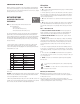
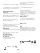
COMPLETION OF INSTALLATION Wiring Notes When the desired focus is achieved for each camera, adjust the segmented bracket arms to the desired viewing angle. Once you've finished, put the dome back in place and check to be sure none of the cameras touch the dome. If one or more do, readjust the arm(s) until they are clear of the dome. Wire — What to DO NVT INSTRUCTIONS 1. DO use point-to-point Unshielded Twisted Pair wire, gauge 24 or thicker, stranded or solid, Category 2, 3, 4, or 5. 2.
3
TROUBLESHOOTING If you experience problems with the camera picture please check these simple troubleshooting procedures for possible solutions before calling technical support. STATIONARY OR SCROLLING HORIZONTAL LINES ON SCREEN GROUND LOOPS Generally a horizontal line on screen, whether moving or stationary, means you have a ground loop problem. The video shield should only be connected to ground through the monitor or other electronic equipment that uses the video signal.
NVT TROUBLESHOOTING If you are experiencing problems, attempt to simplify your setup. Test each cable segment separately. For example, test the camera and monitor together without the other equipment. Then add in the NVT transceivers, back-to-back. Test each segment of a long cable-run independently. Attempt to isolate the problem. Below are problems that may be encountered. If the suggestions below are not helpful, or the recommendations are not effective, please call NVT’s customer support.
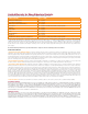
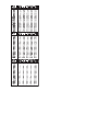
CABLE AND POWER GUIDELINES This chart shows the proper current needed for power supplies for Q-View Series cameras. Use Class 2 Power only. Input voltage must be 24 VAC/VDC. CAMERAS CURRENT POWER 1 24 VAC/VDC VOLTAGE 102mA 2.5W 2 24 VAC/VDC 210mA 5W 3 24 VAC/VDC 331mA 7.9W 4 24 VAC/VDC 487mA 10.
Product Registration/Warranty Thank you for choosing Moog Videolarm. We value your patronage and are solely committed to providing you with the highest quality products available and superior customer service. Should a problem arise, rest assure that Moog Videolarm stands behind its products by offering impressive warranty plans: 3 Years on all Housings, Poles, Power Supplies, and Accessories and 5 Years on camera systems (SView, QView, Warriors), and InfraRed Illuminators.