
Operating instructions


Page No.
1.0 Table of Contents 1
1.1 General Description 1
1.2 Specication 1
1.3 Included Accessories 2
1.4 Location and Description of Controls 2
1.5 Location of Connectors 2
1.6 Connections 3
2.0 Control of Basic Functions 3
2.1 Camera Selection Pan/Tilt Movement 3
2.2 Camera Zoom/ Focus/Iris Functions 3
2.3 Pan/Tilt Movement 3
2.4 Presets 3
2.5 Autotour 4
2.6 Sequencing 4
2.7 Alarms 4
3.0 Menu Items 4
3.1 Dome Selection Type 4
3.2 Multiplexer Type 4
3.3 Preset Lockout 4
3.4 Autotour Dwell 5
3.5 Beep Enable 5
3.6 Sequence 5
3.7 Sequence Dwell 6
3.8 Alarms 6
3.9 Pass Code 6
4.0 PC Port 6
4.1 PC Port Commands 6
4.2 General Command Message Format 6
4.3 Motion Command Messages 6
4.4 Preset and Dome Parameter Messages 7
4.5 Controller Parameter Messages 7
4.6 Custom Controller LCD Messages 7
5.0 Master Unit Function 8
A NOTE BEFORE BEGINNING
Each camera controlled by the VLC485 must have a unique address. The default
address for most cameras is "1". See the instructions for your camera for steps to
change the address.
1.0 TABLE OF CONTENTS
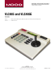
1.1 GENERAL DESCRIPTION
The VLC485 is a pan/tilt controller that ties together the major elements of an
integrated system and provides a single human interface for the system. As such, the
VLC485 can control pan/tilt units, interface to multiplexers, and communicate with a
personal computer for computer-controlled operation.
The LCD is used to display current status as well as to provide a menu system for
setting operational parameters.
The VLC485 is designed for desktop operation; all connectors are located in the rear
of the unit so that all cables can be routed from the back of the unit.
1.2 SPECIFICATIONS
Power Source
Data Connections
Pan/Tilt Control
Camera Control
Multiplexer Control
Alarms
Conguration
Display
External Serial
Communications Port
Operating Environment
4-pin compression connetor: RS485/422
Pan/Tilt control network.
9-pin d-sub connector: RS232 multiplexer
port.
9-pin d-sub connector: RS232 external serial
communications port.
5v DC 250 ma.
Maximum number of pan/tilts: 99.
Protocols: Moog, Sensormatic, Pelco, and
Kalatel.
Manual control: pan, tilt via joystick.
Speed: Variable.
Presets: go to, set, clear.
Autotour (Moog protocol): on, off, set dwell,
set speed.
Manual control: Zoom, focus, iris.
Auto: focus, iris (where supported by
camera).
Protocols: TBD.
Number of channels: up to 32.
Eight external alarm inputs and one relay
contact alarm output.
Menu driven, access controlled by
optional passcode.
LCD, 20 character x 2 lines.
9600 baud, 8 bits, 1 start, 1stop, no
parity
Protocols: Moog.
Temperature: 0˚ C – 50˚ C.
Humidity: 90% maximum
(non-condensing).
Altitude: 10,000 ft. maximum.