IMPORTANT SAFETY INSTRUCTIONS WARNING – When using electric products, basic precautions should always be followed, including the following: 1) Read all the instructions before using the product. 2) Do not use this product near water – for example, near a bathtub, washbowl, kitchen sink, in a wet basement, or near a swimming pool or the like. 3) This product should be used only with a cart or stand that is recommended by the manufacturer.
USER’s MANUAL for the ELECTRIC BLUE By R. Stephen Dunnington Here it is – the Minimoog Voyager® Electric Blue. Over fifty years ago, Robert Moog began a career as a designer of electronic musical instruments. It is no small feat that today he is still creating new and bold designs, using his vast knowledge of musical interaction with electronic circuits.
I. Getting Started For those of you who can’t wait to read the manual (perfectly understandable when you have a brand new synthesizer…), the following are the important steps to get you going with your new Voyager. Once the adrenaline subsides a bit, you will find this manual to be an excellent guide to exploring the outer reaches of your minimoog Voyager.
-Power up Turn the power on. You will see the screen light up and display: “Moog Voyager”. After about 5 seconds the Power-On screen disappears and you will see the current active preset. The LED labeled “PANEL” will be lit. The buttons labeled “PANEL”, “EDIT”, and “MASTER” access the 3 operating modes of the Voyager. PANEL is the Mode for playing the Voyager’s Presets. -Check out the Blue Backlit Panel The knob next to the highest C on the keyboard is the intensity control for the Blue Backlit Panel.
-Start Playing! The quickest way to hear what the Voyager has to offer is to listen to the presets. Pressing the +1 or –1 buttons will access a new preset. If the sound does not change, then “Quick mode” is not active – simply press ENTER to load the new sound. Presets 001 – 128 are loaded with sounds from the factory. There are a total of 128 locations in memory for presets – all are user programmable. Note that once a preset is called up, you can tweak the parameters to your liking.
II. THE BASICS OF ANALOG SYNTHESIS For those getting started in the world of electronic music, let’s take a few moments to go through the basics of sound and synthesis. This will help you understand what the front panel controls do. In order to understand synthesis, one must have a basic working knowledge of the characteristics of sound. There are a few key terms that cover the basics: Sound – audible vibrations of air pressure. Electronic sounds are delivered to the air through loudspeakers.
Amplitude – The strength of a sound’s vibration measured in Decibels (dB). This corresponds to the musical term Loudness (figure 4). Harmonic Content – A sound is made up of simple vibrations at many different frequencies (called harmonics) which give a sound its particular character. This corresponds to the musical term timbre or tone color. A harmonic sound, such as a vibrating string, is one in which the harmonics are mathematically related by what is called the harmonic series.
In general, “synthesis” refers to the generation of sound through a group of amplified circuits over which the programmer/performer has power to change volume, pitch, timbre and articulation. The Minimoog Voyager is based on what is called “subtractive synthesis”. This method of synthesis employs a harmonically rich (think bright-sounding) source material, and then removes frequency components to create the desired sound.
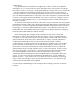
Filter: A circuit that removes some frequencies and allows other frequencies to pass through the circuit. A filter has a cutoff frequency that determines the point at which frequencies begin to be removed. A lowpass filter is one in which frequencies above the cutoff frequency are removed and all frequencies below the cutoff are passed through. A highpass filter is one in which frequencies below the cutoff frequency are removed and frequencies above the cutoff are passed through.
Control Voltage - Control voltages (also called CVs) are used in analog synthesizers to affect changes in the sound. In the case of pitch, pressing a key on the keyboard sends a control voltage that determines the pitch of the oscillators. The pitch can also be changed by a voltage provided from a panel control, such as an oscillator tuning control. Every panel control on the Voyager produces a control voltage that is routed to the circuit that the knob or slider is designed to change.
modulate filter cutoff. Modulation is used in synthesis to create complex sounds and add variation. Envelope Generator - An envelope describes the contours that affect the characteristics of a sound as it evolves in time from its start to its finish. Take a plucked string for example: when a string is plucked, its amplitude is suddenly very loud, then dies out gradually. The initial part of the sound is very bright but then the brightness fades away.
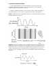
For instance - an LFO with a triangle waveform at about 6 Hz modulating the pitch of a VCO sounds like vibrato. The same LFO with a square wave will sound like a trill (figure 10). An LFO modulating a voltage controlled amplifier will sound like a tremolo. Sample and Hold - This is a circuit with an input for a control voltage and an input for a trigger.
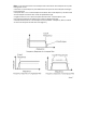
III. The Voyager’s Features The minimoog Voyager is a monophonic analog synthesizer that is a descendant of the classic minimoog. Its sound sources are an external audio input, a noise source, and three analog, variable waveform oscillators. The Voyager has front panel controls for real time control of its parameters (figure 12).
The back panel offers the many connections available, including the power, MIDI, CV, and audio connections (figure 13). For the Control Inputs, a blue nut indicates a gate/footswitch input and a red nut indicates a CV/ expression pedal input. - The Oscillator section includes controls for choosing the octave, the tuning of the second and third oscillators, the oscillators’ waveforms, and switches for oscillator sync, linear FM, and oscillator 3’s frequency range and keyboard control.
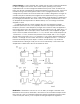
- When a key is pressed, A Gate and Pitch CV are produced by the keyboard. The Gate signal is used to trigger both the Filter and Volume Envelopes. The Pitch CV is used to determine the pitch of the Oscillators and can be applied to a varying degree to the Filters through the Keyboard Control Amount knob (fig 15). - Modulation is performed through the Modulation Busses. There are two separate Mod busses. One is controlled by the Mod Wheel, while the other is controlled by the MOD1 CV input.
- The LFO is assigned through the MOD Busses. It features a triangle and square wave. It is also used to trigger the Sample and Hold. - The touch surface controller can generate three continuous control signals (X,Y,A) simultaneously, and a gate is produced when the surface is touched. The position of a finger on the touch pad generates a control voltage for horizontal (X) position and a control voltage for vertical (Y) position.
IV. The Voyager’s Components A. MIXER The Mixer combines the main sound sources of the Voyager. It’s the place to start when creating a new sound from scratch, or figuring out how a sound is put together. All the sound sources can be turned on or off, and their levels can be adjusted. The sound sources available are: - External Audio Input - Oscillator 1 - Oscillator 2 - Oscillator 3 - Noise Source Each sound source has both an on/off switch and a level control.
EXTERNAL AUDIO IN: The External Audio in allows an external audio source to be routed into the mixer, where it can be mixed with the VCOs and Noise source, then passed to the filters and the out put. The LED above the External input begins to light up as the Input signal to overdrives the Mixer input. When the light is faint, a small amount of soft clipping is occurring. When the LED is bright, the signal is really strongly overdriven. Judicious use of overdrive can really fatten up a sound.
B. OSCILLATORS The Oscillators are the main sound source of the Voyager. The oscillators in the Voyager are all analog Voltage Controlled Oscillators, or VCOs. They feature a temperature regulation circuit that provides them with excellent tuning stability. The VCOs can produce a total musical range of 8 ½ octaves! In addition, the frequency of oscillator 3 can be set to sub-audio (<20Hz) vibrations for use as a second LFO.
relative to Osc. 1. This allows more than one frequency to be played when a key is pressed, or to get a very swirly sound when the oscillators are slightly out of tune. Oscillator 1 does not have a frequency control because it is designed to serve as a reference oscillator for the other 2 oscillators. FINE TUNE: Fine tune control can be used to tune the Voyager’s oscillators + or – 2 semitones for matching an external reference pitch.
3 Æ 1 FM: Direct Linear Frequency Modulation of Osc. 1 by Osc. 3 When an Oscillator is used as a CV source for another VCO, it is called Frequency modulation. Frequency Modulation effects can vary from vibrato or trill effects to clangorous inharmonic sounds to rich timbres that evoke acoustic sounds. Linear FM is the kind of Frequency Modulation used in classic FM synths. GLIDE: Glide enables a glissando effect between notes. There is a switch on the left hand controller panel that enables this effect.
C. FILTERS Ahh… the Moog filter – the sound that started it all… Filters are used for transforming the character of an audio signal. Filters modify a sound by stopping some frequencies and allowing others to pass through. An important term regarding filters to understand is “Cutoff Frequency”. This is a frequency at which frequencies begin to be rejected. There are different types of filters. Some of the most common and most musically useful are lowpass, highpass, and bandpass.
When the resonant peaks of the lowpass filters pass through the overtones of the sound being filtered, those overtones are reinforced. This gives the filter a nice character that sounds vocal, quacky, or zappy, depending on how it’s used. When the resonance is turned up past 8, the filters begin to self-oscillate at the cutoff frequency, producing a sine wave tone. The Keyboard Control Amount control sets how much the filters’ cutoff frequencies track the keyboard note that is played.
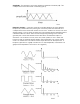
HIGHPASS LOWPASS MODE: In Highpass/Lowpass mode, the Voyagers filters are configured as a lowpass and highpass filter in series, summed to both outputs. As with the dual lowpass mode, the Cutoff control changes the cutoff frequency of both filters, and the spacing sets the frequency difference between the highpass filter and lowpass filter. The spacing between the two filters creates a bandpass filter (figure 21).
SPACING: The Spacing control is used to determine the difference between the cutoff frequencies of the two filters in both dual lowpass mode and highpass/ lowpass mode. In Dual Lowpass mode, the numbers on the legend around the knob refer to octaves. When the Spacing control is centered, the cutoff frequencies of the two filters are identical and the filter sounds like a classic Moog Filter.
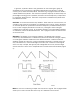
D. ENVELOPES When we think of a musical sound, say a plucked string, we think of it as having a start and an end. In the case of a plucked string, it begins with a burst of energy and then slowly fades out until it is silent. In synthesis terms, this is called an envelope – a shape that defines the changes that occur in a sound over time. An envelope can define any aspect of a change in sound – volume, timbre, or pitch for example. The Voyager has two envelope generators.
DECAY: This Control sets the Decay time of the EGR from 1 msec to 10 seconds. SUSTAIN: This is a level control for the sustained part of the envelope. RELEASE: This is the time for the envelope to return to zero, from 1 msec to 10 seconds. AMOUNT TO FILTER: For the filter envelope, this is the control that adjusts the amount that the filter envelope signal modulates the filter. It has both positive and negative values. If it is set to a positive value, say +2, The envelope will add to the Cutoff control.
ENVELOPE GATE INPUT: This input accepts a footswitch or gate signal. Pressing the footswitch or applying a gate signal (+5V) triggers both envelopes when On/External is selected by the ENV. GATE switch. RELEASE INPUT: This input accepts a footswitch or gate signal. Pressing the footswitch or applying a gate signal (+5V) enables the Release of the Envelopes regardless of the position of the Release switch on the Left Hand Controller panel.
E. MAIN OUTPUT The Voyager has two audio outputs. There is a VCA for each output, which allows for stereo effects such as Panning or the Dual lowpass filtering. The main control for the Volume is the Master Volume Control. The Volume Envelope modulates the output VCAs. When only one output is desired, the two output VCAs are mixed to the left output. LEFT/MONO and RIGHT OUTPUTS: These are the audio outputs that are on the back panel. They are both ¼” unbalanced outputs.
F. MODULATION BUSSES Modulation is the heart of making interesting sounds with analog subtractive synthesis. The Voyager’s two Modulation busses open up a world of modulation possibilities that were not available on the original Minimoog. The Mod Busses allow the user to select a variety of modulation sources, their destinations, addition shaping of the amount of modulation, and a maximum level. The Mod busses are labeled Mod Wheel and Pedal/On.
There are three modifiers to the Amount of modulation: the Amount control, the Shaping CV, and the Mod Wheel or MOD1 input level. The Amount level is the final level control which sets how much both the Mod Wheel/ MOD1 Input and the shaping CV allow the mod source through to the mod destination. To try out a simple modulation, set the LFO to about 6 Hz, the Source to triangle wave, the destination to Pitch, the shaping to on, and the amount to 5.
comes out of the keyboard is either on or off, thus pressure can be used as a switch that gives a boost to the amount of modulation. - ON/PGM: This is a programmable shaping for the mod bus with ON as the default. Shaping sources can be programmed in EDIT mode using the “PGM Shaping 1 SRC” and “PGM Shaping 2 SRC” functions. AMOUNT: The Amount control is used to set the maximum amount of modulation sent to the Modulation Destination.
G. LFO/ SAMPLE AND HOLD The Voyager has a dedicated LFO and SAMPLE and HOLD. The LFO produces triangle and square waves that oscillate from .2 to 50 Hz. There are triangle and square wave outputs that can be selected as Modulation sources in the Mod Busses. The Square wave is routed to the Sample and Hold trigger input, and the noise source is routed to the sample and hold input. For each cycle of the LFO, the voltage at the input of the sample and hold circuit is held until the next trigger event.
LFO SYNC: The LFO Sync switch sets the trigger method for starting the LFO waveform. OFF/SYNC: This setting allows the LFO to be free running, unless there is an input to the SYNC jack on the back panel. The SYNC jack accepts a +5 V Clock Signal that retriggers the LFO. MIDI: Allows a MIDI clock signal to retrigger the start of the LFO cycle. KB: Allows the LFO to be retriggered when a note on the keyboard is started. ENV.
H. KEYBOARD AND LEFT HAND CONTROL PANEL The Voyager has a 44 note keyboard (3 ½ octaves F to C), like the original minimoog. Unlike the original minimoog, the keyboard can produce velocity CVs, a pressure CV, and transmit MIDI note on and note off messages. To the left of the keyboard is the Left Hand Controller Panel. It features the Pitch Bend and Mod Wheel controls and the glide and release switches.
I. TOUCH SURFACE CONTROLLER The touch surface controller is a real-time three-dimensional control surface. It can be used to impart complex gestures to the sound of the Voyager by touching it, moving a finger around on it or tapping it. A movement from left to right is the X-axis, up and down is the Y-axis, and the amount of area covered is the third control signal generated, called ‘A’.
J. THE BACK PANEL The Back Panel is loaded with Jacks. In addition to the Audio Outputs, there are a multitude of CV and gate inputs, the MIDI connectors, a BNC outlet for a gooseneck lamp, the accessory port, and the power connector. POWER CONNECTOR: This is a standard AC power inlet, Use only a power cord designed to mate with this receptacle. The Voyager power supply is designed to work with power inputs of 100-240 VAC. DANGER – Do not alter this connector in any way.
K. THE USER INTERFACE/ VOYAGER SOFTWARE VERSION 2.5 1. The Interface The interface for the minimoog Voyager’s software functions is in the center of the instrument (figure 25). (figure 25) The display is a LCD screen in the center. When the unit is first powered on, the screen will read the message: The message will stay on the screen for approximately 5 seconds, then the screen will display the current active preset. Note that the LED above the button labeled “PANEL” is lit.
2. MASTER Mode MASTER mode accesses the global settings for the Voyager and the routines for sending and receiving data. To enter MASTER mode, press the MASTER button. The following is the Master Menu: 1.1 LCD Contrast 1.2 MIDI Local Keyb. 1.3 MIDI Merge Func. 1.4 MIDI Prg. Change 2.1 MIDI In Channel 2.2 MIDI Out Channel 2.3 MIDI In ON/OFF 2.4 MIDI Out ON/OFF 3.1 Send Panel Sound 3.2 Send All Presets 3.3 Receive Presets 3.4 SysEx Device ID 4.1 Transpose In/Out 4.2 MIDI Key Order 4.3 Velocity Curve 4.
internally generated MIDI messages. When sequencing, this function should be turned off to prevent “double triggering” caused by a MIDI loop. 1.4 MIDI PRG. CHANGE Program Change Receive On/Off. This enables or disables the Voyager’s reception of MIDI program changes. When this is off, only the +/- 1 buttons change the Voyager’s presets. 2.1 MIDI IN CHANNEL When this is selected, use the +1/ -1 buttons to select the MIDI Channel that the Voyager recognizes. The Voyager only responds to one channel at a time.
utility will replace any presets that are in memory, so be sure to back up any presets you want to save before going through this process. 3.4 PROGRAMMABLE SYSEX DEVICE ID This function can be used in a situation where more than one Voyagers are in a setup. By Changing the SysEx Device ID, when a Preset Bank is sent, the Device ID byte in that SysEx message matches the Device ID set in that Voyager.
velocity output from the keyboard. Hard requires a harder touch to output higher velocity values. 4.4 COPYRIGHT INFO/ FACTORY SETUP MENU Copyright Info, shows the copyright dates, as well as the author of this software, Rudi Linhard (Thanks, Rudi!). This is the entry page to the Factory Setup menu – simply press the +1 button to see the Factory Setup Menu. These functions are used for initializing parameters in the Voyager’s Preset bank.
The “Clock Divider” function restores the default settings for the clock divider parameter stored in the presets. The default value is “24”, which is an 8th note (half a beat). To restore the clock divider values to their defaults, select the function “Clock Divider” and press ENTER. The screen will prompt: “Reset the Clock Divider Values of all Preset Sounds? Yes/No” Select Yes and press ENTER. 2.
- MIDI Software capable of sending a generic Sysex bank file (.syx) or Standard MIDI file (.mid) Many sequencers are capable of opening Sysex files and sending Sysex data. If you do not own one of these, check out “MIDI-OX”, a MIDI utility software for PC available online at www.midiox.com. For Mac, there is a program called “Sysex” that provides the same function. Many sequencers can be used to import the Standard MIDI file versions (.mid) of the software.
3. EDIT Mode EDIT Mode is used to determine parameters of a preset not accessible through the front panel and to name and save presets. EDIT mode is entered by pressing the EDIT button. When this is done, a list appears that displays the different options. Using the +1 or –1 buttons moves the cursor to highlight a new line. There are four items per page, and 6 pages. The page number and item number are displayed in the EDIT menu. The Options in EDIT mode are: 1.1 Compare to Preset 1.2 Recall last Sound 1.
RECALL will be highlighted. Press ENTER, and the display will prompt “Recall the last edited sound? Yes/No”. Use the cursor button to select Yes and press ENTER. You will now hear the changes you made to the preset. At this point if you want to keep those changes, you can save the preset. RECALL can also be used to return to a preset sound after the parameters are initialized (INIT. PARAMETERS or REAL PANEL CONTROL see below). 1.3 REAL PANEL CONTR.
PROGRAMMABLE MOD WHEEL DESTINATION is a function that allows the user to program 1 of 8 additional modulation destinations to be used when the DESTINATION switch for the Mod Wheel Mod Bus is set to LFO RATE/PGM. Enter EDIT mode, and use the +1 button to highlight PGM M-WHL DEST. Press ENTER and the following Mod Destinations appear: LFO Rate (default) Filter Resonance Filter Spacing Panorama Osc. 1 Level Osc. 2 Level Osc. 3 Level Noise Level 2.
the Mod Source is let through to the Destination. The Programmable Shapers also allow an offset value to be applied, added to the Shaper itself. Using the programmable Shapers is useful for creating presets that respond in complex ways – for instance – you could assign BOTH key pitch and velocity as your programmable shaping sources. In this case, the higher and the harder you play, more modulation source is passed to modulate the destination. Many of the Shaping sources are front panel rotary controls.
- Headphone Volume The Fixed Value can be used by itself or added to one of the Shaping sources. It has a course adjustment, called “High” and a Fine adjustment, called “Low”. Both the High and Low values are adjustable from -64 to +64. The CURSOR button moves the cursor between the Shaping Source, the High fixed value and the low fixed value. 3.3 KEYBOARD MODES KEYBOARD MODES allows the user to select 1 of 4 types of keyboard priority for a preset.
− Gate is OFF 5.1 T.S. DESTINATION Touch Surface Destination. Highlighting this item and pressing ENTER accesses a menu that shows the different outputs of the Touch surface: X, Y, A, Gate. The screen looks like this: Touch Surface X Touch Surface Y Touch Surface A Touch Surface Gate Use the +/- 1 button and selecting an output, then press ENTER. The display shows something like this: Dest: Fil Cutoff MIDI Ctrl. No.
− − − − − − − volume attack volume decay volume sustain volume release key cv (pitch of all 3 oscillators across range of keyboard) osc 1 octave (pitch of single oscillator across range of keyboard) osc 2 octave (pitch of single oscillator across range of keyboard) − osc 3 octave (pitch of single oscillator across range of keyboard) T.S GATE: − − − − − − − − − − − − − − No Switch (default) Glide Switch Release Switch Osc. 1Æ 2 Sync switch Osc. 3-Æ1 FM switch Osc. 3 KB Control switch Osc.
that axis does not modulate the destination. 50% means that the amount of the touch surface output adds 50% of the total range of that control to its present value. For example, if the Filter cutoff is the destination of touch surface x, the amount is set to 50%, and the Cutoff knob is fully counter clockwise, the maximum X value (all the way to the right) would make a change in the filter cutoff equal to turning the Cutoff knob to the mid-position.
− − − − − − − − − − − − − − − − − − − − − − Osc. 3 Octave Osc. 3 Waveform Ext. Audio Level Osc.1 Level Osc. 2 Level Osc. 3 Level Noise Level Filter Cutoff Filter Spacing Filter Resonance Filter KB Control Amount Filter Attack Filter Decay Filter Sustain Filter Release Filter Envelope Amount Volume Attack Volume Decay Volume Sustain Volume Release Master Volume Headphone Volume Available Pot Mapping Destinations are: − − − − − − − − − − − − − − − − − − − − − − − − − − Pitch Bend Mod.
− − − − − − − − − − − − − − Filter Spacing Filter Resonance Filter KB Control Amount Filter Attack Filter Decay Filter Sustain Filter Release Filter Envelope Amount Volume Attack Volume Decay Volume Sustain Volume Release Master Volume Headphone Volume The next parameter available in Pot Mapping is Direction. Choices are Normal or Inverted. Normal means, as the value of a Source is increased, the value to the Destination is also increased.
The default settings for the rest of the Voyager’s parameters are as follows: pitch bend amount ----- fourth keyboard mode --------- lower key priority trigger mode ---------- single trigger filter a -------------- 4 pole filter b -------------- 4 pole filter env gate ------- env gate input (jack) amplitude env gate ---- env gate input (jack) touch surface x dest. - filter cutoff touch surface x ctrl. - off touch surface x dir. -- normal touch surface x amt. -- 50% touch surface y dest.
pot map 2 source ------ key pitch pot map 2 dest. ------- filter resonance pot map 2 direction --- inverse pot map 2 amount ------ off pot map 3 source ------ mod. wheel pot map 3 dest. ------- filter spacing pot map 3 direction --- normal pot map 3 amount ------ off pot map 4 source ------ foot pedal 1 pot map 4 dest. ------- filter cutoff pot map 4 direction --- normal pot map 4 amount ------ off midi clock divider ---- 24 preset name ----------- "Preset xxx" (xxx = act.
A B a b C D c d cursor backward E e F G H I f g h i space * = “ . : J j , ; K k ! ? L M l m 1 2 - + N O n o P Q p q 3 4 5 % # & R S r s T t 6 < U u 7 > V v W X Y Z w x y z 8 ( 9 / 0 ) cursor forward shift Once a name is entered, it must be saved to be stored in memory. Below is the routine for saving presets. 6.
4. PANEL Mode PANEL Mode is used to access presets and other performance functions. Pressing the PANEL button accesses PANEL mode. This lights the LED above the PANEL button, and the preset number is displayed. Note that the previous sound is stored until the ENTER button or the +1/-1 buttons are pressed. Once a preset is called up, parameters can be changed. If the original sound is desired, simply press ENTER and the original preset will be reloaded.
This does not appear as an option in the Panel Menu – but is used in conjunction with “Receive Presets” in Master Mode. In Master Mode, make sure Sysex is enabled in “Receive Presets”. Once this is done, a single preset can be received to the current active preset location in Panel mode. Once a preset is received in the current active location, it can be auditioned. If you want that preset to become part of the Voyager’s preset bank, you must save the imported preset.
5. MIDI Software Version 2.0 for the minimoog Voyager contains an extensive MIDI implementation. The MIDI channel for transmission and reception is selected in the MASTER mode. It is remembered after power down. MIDI Transmission and Reception includes: Note On messages: The Voyager is a monophonic synthesizer, and responds to Note On messages based on the Note Priority and Trigger Mode selected. Note On messages are transmitted polyphonically.
Osc. 1 Octave Osc. 1 Waveform Osc. 2 Frequency Osc. 2 Octave Osc. 2 Waveform Osc. 3 Frequency Osc. 3 Octave Osc. 3 Waveform 1Æ 2 Sync 3Æ 1 FM 3 KB Control 3 Frequency Lo/Hi External Audio Level External Audio On/Off Osc. 1 Level Osc. 1 On/Off Osc. 2 Level Osc. 2 On/Off Osc. 3 Level Osc.
MIDI CLOCK When the LFO SYNC switch is set to “MIDI”, a MIDI clock signal retriggers the start of the LFO cycle, similar to the way Oscillator Sync works. Because the Voyager has an analog LFO – the LFO Rate itself is not automatically set to the clock frequency – just the start of the LFO cycle. Adjusting the LFO Rate to a different rate relative to the MIDI clock signal can yield some interesting LFO patterns.
Appendix A: Caring for your Electric Blue Voyager Clean the Voyager with a soft, moist cloth only – do not use solvents or abrasive detergents. The finish of the wood cabinet can be cleaned with a guitar polish, or a fine furniture polish. Heed the safety warnings at the beginning of the manual. Don’t drop the unit. If shipping your Voyager, we recommend the original shipping carton, or an ATA approved Road Case.
Appendix C: MIDI IMPLEMENTATION CHART Moog Music Inc.
Appendix D: VX-351 User’s Guide Introduction Flash back to the late 60’s…. Back in the day, a synthesizer was a behemoth of panels and patch cords. They were known as modular synthesizers, because each function of the synthesizer was contained in a single module. A synthesizer was a collection of modules, and the instrument produced no sound until the proper connections were made by patch cables, from module to module.
- Getting Started - Understanding the VX-351 - Documenting your work - Using the VX-351 and the minimoog Voyager together - Adding a moogerfooger® CP-251 to the mix… - Connecting other CV compatible equipment. - Technical Information GETTING STARTED with the VX-351 Important! Please read the instructions before attempting to use the VX-351 with your minimoog Voyager! 1) Inspect the contents of the carton. It should include: - The VX-351 - A 6’ cable with db-25 connectors on each end.
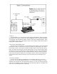
3) Now let’s start with a basic sound and see how the VX-351 can work with the Voyager. - Power up the Voyager – press the EDIT button. - In the EDIT menu select “Init. Parameters”, press ENTER, select YES and press ENTER again. This loads the default Voyager sound. - Take one of your ¼” cables – plug one end into the VX-351’s LFO triangle output. Plug the other end into the Voyager’s Filter control input. - Play a note on the Voyager – you will hear the LFO modulating the Filter’s Cutoff.
Understanding the VX-351 The VX-351 is organized by section – similar outputs are grouped together. Here’s the rundown… TOUCH This group of outputs is generated from the Touch Surface Controller. There are three CVs (X, Y, and A) and one gate signal. X: This is the CV generated by left to right (horizontal) position of contact with the touch surface. Y: This is the CV generated by up and down (vertical) position of contact with the touch surface.
LFO: This group of outputs is generated from the Voyager’s LFO (Low Frequency Oscillator) circuit. There are two CV waveforms here – triangle and square TRIANGLE: This is the triangle wave output of the LFO. SQUARE: This is the square wave output of the LFO. BUSSES: This group of outputs is generated by the Mod Buss signals.
Documenting your work One thing to keep in mind is that although the Voyager can remember the settings of the front panel controls as a preset, it cannot save the routings of patch cables or the positions of the attenuators.
Using the VX-351 and the minimoog Voyager together The following are some ideas for using the VX-351 with the minimoog Voyager. A) Mod wheel controls amount of both Mod Buss signals. This is a really useful way to use the Mod Wheel as a controller for more than one type of modulation. To try this out, go through the following steps: - Initialize the Voyager’s parameters (Init. Parameters in the Edit Menu) - Set the Pedal/On Mod Buss Source to Square wave, set the Pedal/On Destination to Filter.
- Initialize the Voyager’s parameters - Using a ¼” cable, connect the VX-351 LFO Square Output to the Voyager’s Envelope Gate Input. - Switch the Envelope Gate switch at the bottom right corner of the front panel to “On/External”. You should immediately hear a note repeating at the LFO rate. These are just a few examples of the functions that a VX-351 adds to a Voyager. Adding a moogerfooger CP-251 to the mix The VX–351 works incredibly well alongside the moogerfooger CP-251 Control Processor.
C) Sample and hold staircase patterns A Sample and Hold circuit can be used for more than generating random voltages. One type of modulation pattern that can be achieved is called “Staircase” modulation. It is achieved by feeding a slow triangle wave into the sample and hold input – with a trigger signal like a LFO at a faster rate, the output looks like the triangle wave is chopped up into “stairs” at the trigger LFO rate. - Initialize the Voyager’s parameters. Set the Voyager’s LFO rate to about .8 Hz.
Connecting other CV compatible equipment We’ve covered some basic uses of the Voyager and the VX-351 – and even added a CP-251 to the mix. Other CV compatible equipment like our moogerfooger analog effects can be added to liven up the proceedings. Other CV compatible equipment can be connected as well. Keep in mind that you should always connect a source to a destination, and that you shouldn’t combine multiple CVs to a single destination without a mixer.
MOD2: -5 to + 5 V, +5 V w/nothing connected to MOD 2 input. 330 Ω output impedance. LFO TRIANGLE: -2.5 to +2.5 V, 330 Ω output impedance SQUARE: 0 to +3 V, 330 Ω output impedance BUSSES WHEEL: Max. Outputs –4 to +4 V Nominal, 1000 Ω output impedance. PEDAL: Max. Outputs –4 to +4 V Nominal, 1000 Ω output impedance. ENVS FILTER: 0 to +5 V, 330 Ω output impedance. VOLUME: 0 to +5 V, 330 Ω output impedance. S&H STEP: Max. -2 to +2 V Nominal, 330 Ω output impedance. SMOOTH: Max.