USER’s MANUAL for the Rack Mount Edition By R.Stephen Dunnington Here it is – the Minimoog Voyager Rack Mount Edition®. Moog Music has put more than 30 years of experience with analog synthesizer technology into the design of this instrument to bring you the fattest lead synthesizer since the minimoog was introduced in 1970. We’ve done away with the things that made 30-yearold analog synthesizers difficult – the tuning instability, the lack of patch memory, and the lack of compatibility with MIDI gear.
I. Getting Started For those of you who can’t wait to read the manual (perfectly understandable when you have a brand new synthesizer), the following are the important steps to get you going with your new Voyager. Once the adrenaline subsides a bit, you will find this manual to be an excellent guide to exploring the outer reaches of your minimoog Voyager.
- Connect to Amplifcation Make your connections to your Amplifier, Mixer, or Powered Monitors, or simply connect Headphones. Turn the volume control of your amplification all the way down. - Power up Turn the power on. You will see the screen light up and display: “Voyager by moog music”. After about five seconds the greeting screen disappears and you will see the current active preset. The LED labeled “PANEL” will be lit.
use, and turning the lamp OFF when not in use. A small amount of high-pitched acoustic noise is transmitted from both the power supply and the lamp themselves when the lamp is driven hard. This sound doesn’t appear at the Voyager’s outputs. Reducing the brightness of the lamp reduces the transmission of the sound from the power supply and lamp. See Appendix A for more information about the Voyager Rack Mount’s lamp.
II. THE BASICS OF ANALOG SYNTHESIS For those getting started in the world of electronic music, let’s take a few moments to go through the basics of sound and synthesis. This will help you understand what the front panel controls do. In order to understand synthesis, one must have a basic working knowledge of the characteristics of sound. There are a few key terms that cover the basics: Sound – audible vibrations of air pressure. Electronic sounds are delivered to the air through loudspeakers.
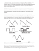
Amplitude – The strength of a sound’s vibration measured in Decibels (dB). This corresponds to the musical term Loudness (figure 4). Harmonic Content – A sound is made up of simple vibrations at many different frequencies (called harmonics) which give a sound its particular character. This corresponds to the musical term timbre or tone color. A harmonic sound, such as a vibrating string, is one in which the harmonics are mathematically related by what is called the harmonic series.
In general, “synthesis” refers to the generation of sound through a group of amplified circuits over which the programmer/performer has power to change volume, pitch, timbre and articulation. The Minimoog Voyager is based on what is called “subtractive synthesis”. This method of synthesis employs a harmonically rich (think bright-sounding) source material, and then removes frequency components to create the desired sound.
- A lowpass filter is one in which frequencies above the cutoff frequency are removed and all frequencies below the cutoff are passed through. - A highpass filter is one in which frequencies below the cutoff frequency are removed and frequencies above the cutoff are passed through. - A bandpass filter has two cutoff frequencies that define a frequency band, outside of which the frequencies are removed (figure 7).
one octave. The VCF CV is dropped 6 volts to –1 V. Notice that the cutoff frequency then drops 6 octaves, and at 250 Hz, only allows the fundamental tone through. Finally, the VCA CV is reduced by 3 Volts. Notice the amplification is reduced to 40% of the maximum level. Modulation - Modulation is the use of a CV to affect a voltage-controlled circuit. Modulation has a source, destination, and amount.
Attack, measured in time, specifies the onset or transient of a sound. With Volume for instance, the sound might start suddenly as does a plucked string sound, or fade in slowly like a bowed string crescendo. Decay is also measured in time and specifies how quickly the onset of a sound fades into the sustained portion. Sustain is the level at which a sound sustains after the initial transient. Release is measured in time and determines how long a sound takes to fade away after a note is released.
Sample and Hold - This is a circuit with an input for a control voltage and an input for a trigger. Each time the trigger is fired, the circuit takes the voltage that appears at the input and holds it at the output until the next time the circuit is triggered. An LFO is a common way to trigger a sample and hold (or S&H) circuit.
III. MIDI Basics MIDI stands for “Musical Instrument Digital Interface” and was established over 20 years ago to give musicians a standard interface for interconnection and control of synthesis gear. Prior to MIDI, most synthesizer control interconnections were analog CV/gate based, and their standards often varied from manufacturer to manufacturer. A MIDI connection has standard hardware, as well as defines a variety of standard digital messages that are sent through a MIDI connection.
IV. The Voyager’s Features The Voyager’s Front and Rear Panel The minimoog Voyager is a monophonic analog synthesizer that is a descendant of the classic minimoog. Its sound sources are an external audio input, a noise source, and three analog, variable waveform oscillators. The Voyager has front panel controls for real time control of its parameters (figure 12).
The back panel offers the many connections available, including the power, MIDI, audio, and CV expansion connections (figure 13). The Voyager’s Analog Synthesis Engine - The Oscillator section includes controls for choosing the octave, the tuning of the second and third oscillators, the oscillators’ waveforms, and switches for oscillator sync, linear FM, and oscillator 3’s frequency range and keyboard control. - The sound sources are selected and their levels are set in the Mixer section.
- When a MIDI Note On is received, a Gate and Pitch CV are produced. The Gate signal is used to trigger both the Filter and Volume Envelopes. The Pitch CV is used to determine the pitch of the Oscillators and can be applied to a varying degree to the Filters through the Keyboard Control Amount knob. This basic control path is illustrated in figure 15. - Modulation is performed through the Modulation Busses. There are two separate Mod busses.
The Voyager’s Digital Features - The Voyager Rack has three operation modes: PANEL, EDIT, and MASTER. PANEL mode is used for accessing and performing with the Voyager’s 128 User-writable presets. PANEL mode has a menu that can be accessed for performance related functions such as “parameter display” which shows stored and edited values as you edit a preset.
IV. The Voyager’s Components A. MIXER The Mixer combines the main sound sources of the Voyager. It’s a good place to start when creating a new sound from scratch, or figuring out how a sound is put together. All the sound sources can be turned on or off, and their levels can be adjusted. The sound sources available are: - External Audio Input - Oscillator 1 - Oscillator 2 - Oscillator 3 - Noise Source Each sound source has both an on/off switch and a level control.
bright, the signal is strongly overdriven. Judicious use of overdrive can really fatten up a sound. The external audio input can accept a signal from instrument level to line level. MIX-OUT LOOP: The jack on the back labeled “mix out/filter in” is an insert point between the Mixer output and the filter input. Using a standard insert cable an effect such as a moogerfooger® MF102 Ring Modulator can be inserted to add effects to the oscillator, noise source, and external audio in prior to the filter stage.
B. OSCILLATORS The Oscillators are the main sound source of the Voyager. The oscillators in the Voyager are all analog Voltage Controlled Oscillators, or VCOs. They feature a temperature regulation circuit that provides them with excellent tuning stability. The VCOs can produce a total musical range of 8 1⁄2 octaves! In addition, the frequency of oscillator 3 can be set to sub-audio (<20Hz) vibrations for use as a second LFO.
WAVE: Oscillator waveform control The VCOs of the Voyager feature a continuously variable waveform control. The legend on the front panel shows the pure waveforms that are available. They are triangle, sawtooth, square, and rectangular. The waveform is morphed gradually from one to another as the waveform control is rotated. Because the waveform is voltage controlled, this can be modulated. This generates some very interesting timbral changes.
3 à 1 FM: Direct Linear Frequency Modulation of Osc. 1 by Osc. 3 When an Oscillator is used as a CV source for another VCO, it is called frequency modulation. Frequency modulation effects can vary from vibrato or trill effects to clangorous inharmonic sounds to rich timbres that evoke acoustic sounds. Linear FM is the kind of frequency modulation used in classic FM synths. GLIDE: Glide enables a glissando effect between notes. The knob labeled glide adjusts the rate of glide.
C. FILTERS Ahh… the Moog filter – the sound that started it all… Filters are used for transforming the character of an audio signal. Filters modify a sound by stopping some frequencies and allowing others to pass through. An important term regarding filters is “Cutoff Frequency”. This is a frequency at which frequencies begin to be rejected. There are different types of filters. Some of the most common and most musically useful are lowpass, highpass, and bandpass.
When the resonant peaks of the lowpass filters pass through the overtones of the sound being filtered, those overtones are reinforced. This gives the filter a nice character that sounds vocal, quacky, or zappy, depending on how it’s used. When the resonance is turned up past 8, the filters begin to self-oscillate at the cutoff frequency, producing a sine wave tone. The Keyboard Control Amount control sets how much the filters’ cutoff frequencies track the keyboard note that is played.
HIGHPASS LOWPASS MODE: In Highpass/Lowpass mode, the Voyager’s filters are configured as a lowpass and highpass filter in series, summed to both outputs. As with the dual lowpass mode, the Cutoff control changes the cutoff frequency of both filters, and the spacing sets the frequency difference between the highpass filter and lowpass filter. The spacing between the two filters creates a bandpass filter (figure 21).
SPACING: The Spacing control is used to determine the difference between the cutoff frequencies of the two filters in both Dual Lowpass mode and Highpass/ Lowpass mode. The numbers on the legend around the knob refer to octaves. When the Spacing control is centered, the cutoff frequencies of the two filters are identical and the filter sounds like a classic Moog Filter.
D. ENVELOPES When we think of a musical sound, say a plucked string, we think of it as having a start and an end. In the case of a plucked string, it begins with a burst of energy and then slowly fades out until it is silent. In synthesis terms, this is called an envelope – a shape that defines the changes that occur in a sound over time. An envelope can define any aspect of a change in sound – volume, timbre, or pitch for example. The Voyager has two envelope generators.
AMOUNT TO FILTER: For the filter envelope, there is a control that adjusts the amount that the filter envelope signal modulates the filter. It has both positive and negative values. If it is set to a positive value, say +2, The envelope will add to the Cutoff control. If it is a negative value, say –2, the envelope will subtract from the Cutoff control. KEYBOARD/ ON/EXTERNAL: The Envelopes are started by a gate signal. The envelopes will sustain as long as a gate signal is still present.
E. OUTPUTS The Voyager has two audio outputs. There is a VCA for each output, which allows for stereo functions such as Panning or the Dual lowpass filtering. The main control for the Volume is the Master Volume Control. The Volume Envelope modulates the output VCAs. MASTER VOLUME: This is the main Volume control. Full-clockwise is maximum output, fullcounterclockwise silences the Voyager. HEADPHONE OUTPUT: This is a 1⁄4” TRS jack that outputs the Voyager signal to a pair of stereo headphones.
F. MODULATION BUSSES Modulation is the heart of making interesting sounds with analog subtractive synthesis. The Voyager’s two Modulation busses open up a world of modulation possibilities that were not available on the original Minimoog. The Mod Busses allow the user to select a variety of modulation sources, their destinations, addition shaping of the amount of modulation, and a maximum level. The Mod busses are labeled Mod Wheel and Pedal/On.
There are three modifiers to the Amount of modulation: the Amount control, the Shaping CV, and the Mod Wheel (for the Mod Wheel Mod Buss) or MOD1 level (for the Pedal/On Mod Buss). “Amount” is the level control that sets how much both the Mod Wheel/ MOD1 Input and the shaping CV allow the mod source through to the mod destination. To try out a simple modulation, on the Mod Wheel Buss, set the LFO to about 6 Hz, the Source to triangle wave, the destination to Pitch, the shaping to on, and the Amount to 5.
AMOUNT: The Amount control is used to set the maximum amount of modulation sent to the Modulation Destination. When the Amount control is set to 0, no modulation will pass through to the Modulation Destination. When the Amount is set to 10, The maximum amount of modulation is sent to the Destination when the Performance controller (Mod Wheel or MOD1 level) is all the way up.
G. LFO/ SAMPLE AND HOLD The Voyager has a dedicated LFO and SAMPLE and HOLD. The LFO produces triangle and square waves that oscillate from .2 to 50 Hz. There are triangle and square wave outputs that can be selected as Modulation sources in the Mod Busses. The square wave is routed to the Sample and Hold trigger input, and the noise source is routed to the sample and hold input. For each cycle of the LFO, the voltage at the input of the sample and hold circuit is held until the next trigger event.
H. THE REAR PANEL The Rear Panel contains all the Voyager’s connecitvity. In addition to the Audio Outputs, there are the External Audio Input, Mixer Out/Filter In Insert jack, Accessory port CV/gate inputs and outputs, the MIDI connectors, and the power connector. POWER CONNECTOR: This is a standard AC power inlet, Use only a power cord designed to mate with this receptacle. The Voyager power supply is designed to work with power inputs of 100-240 VAC; 50-60 Hz.
I. THE USER INTERFACE/ VOYAGER RACK MOUNT SOFTWARE VERSION 2.6 1. The Interface The interface for the minimoog Voyager’s software functions is in the upper left of the front panel. (figure 25). (figure 25) The display is a LCD screen in the center. When the unit is first powered on, the screen will read the message: “Moog Voyager” with the current OS version displayed. The message will stay on the screen for approximately 5 seconds, then the screen will display the current active preset.
The +1/ -1 buttons scroll through the list. The list will wrap around when you scroll past the end. When a line is highlighted, it can be selected by pressing the ENTER button. Once a line is selected, the screen displays that option. Press the MASTER, CURSOR or ENTER button to return to the MASTER Menu. 1.1 MIDI PRG. CHANGE Program Change Receive On/Off. This enables or disables the Voyager’s reception of MIDI program changes. When this is off, only the +/- 1 buttons change the Voyager’s presets. 1.
individual Voyager in that setup. To use this feature, select “SysEx Device ID” and press ENTER. The screen will prompt: “System Exclusive ID Number à 1”. Use the + or – buttons to select a number between 1 and 128. 3.1 KEY TRANSPOSE The Key Transpose function can be used independently for MIDI Notes transmitted and received. To use this feature, select “Transpose In/Out”. The screen will prompt: “Keyboard Transpose Semitone(s) ___; MIDI Key Transpose Semitone(s) ___.
well as the Touch Surface Gate. The Default values are: X= Filter Cutoff, MIDI CC = Off, Direction= Normal, TS-X amount 50% Y = Filter Spacing, MIDI CC = Off, Direction= Normal, TS-X amount 50% A = Filter Resonance, MIDI CC = Off, Direction= Normal, TS-X amount 50% Gate = No switch, MIDI CC = 88, Polarity = Normal To initialize the Voyager’s Touch Surface parameters, select the function “T.S. XYAG Dest.” and press ENTER.
“Press Enter to send Boot Data”. The boot software version will be displayed on the bottom line. Before you press enter, be sure the remote device is enabled to receive the data. Pressing ENTER will start the export. 4.4 RECEIVE UPDATE This utility is used to upgrade the system software. Updates will be available from time to time on our website, www.moogmusic.com in Minimoog Voyager section, entitled “software”.
3. EDIT Mode EDIT Mode is used to determine parameters of a preset not accessible through the front panel and to name and save presets. EDIT mode is entered by pressing the EDIT button. When this is done, a list appears that displays the different options. Using the +1 or –1 buttons moves the cursor to highlight a new line. There are four items per page, and 6 pages. The page number and item number are displayed in the EDIT menu. The Options in EDIT mode are: 1.1 Compare to Preset 1.2 Recall last Sound 1.
1.3 REAL PANEL CONTR.: REAL PANEL CONTROL is a function that enables the operation of the Voyager from the front panel. To use this function, enter EDIT MODE by pressing the EDIT button. Press the +1 key to highlight REAL PANEL CONT. and press ENTER. The screen prompts: “Load the actual Panel Parameters Yes/No?” Use the CURSOR button to select Yes and press ENTER. The sound produced when the keyboard is played is now determined by the settings of the front panel controls. 1.4 PITCH BEND AMT.
Osc. 2 Level Osc. 3 Level Noise Level 2.3 PGM PEDAL SOURCE PROGRAMMABLE PEDAL/ON SOURCE is a function that allows the user to program 1 of 8 additional modulation sources to be used when the SOURCE switch for the Pedal/On Mod Bus is set to NOISE/ PGM. Enter EDIT mode, and use the +1 button to highlight PGM PEDAL SOURCE. Press ENTER and the following Mod Sources appear: Noise (default) Filter ENV Amplitude ENV Smoothed Sample and Hold Oscillator 1 Oscillator 2 Touch Surface X Touch Surface Y 2.
- Velocity Release Pressure (AT) Keyboard CV Touch Surface X Touch Surface Y Touch Surface A Mod1 Mod2 LFO Rate Glide Rate Mod.Wheel Amount Pedal Amount Osc.1 Octave Osc. 1 Waveform Osc. 2 Frequency Osc. 2 Octave Osc. 2 Waveform Osc. 3 Frequency Osc. 3 Octave Osc. 3 Waveform Ext. Audio Level Osc.1 Level Osc. 2 Level Osc.
1 Key Only (the first key pressed sounds) 3.4 TRIGGER MODES TRIGGER MODES allows the user to select how the envelopes are triggered when more than one key is pressed on the keyboard. Enter EDIT mode and use the +1 or –1 button to highlight TRIGGER MODES. Press ENTER – the screen will display the current Trigger Mode. The +/- 1 button chooses a different option.
TS-X Amount: 100% The parameters for each touch surface axis are: touch surface destination, the MIDI CC being transmitted, the direction of control, and the amount (for X,Y, and A only). To get back to the Touch Surface menu, press ENTER. To return to the Edit Menu then press CURSOR or EDIT. DEST.: Voyager users can choose one of 32 destinations for the Voyager’s touch surface outputs X, Y and A, and 14 destinations are available for the touch surface gate.
− − − − − Osc.2 On/Off switch Osc. 3 On/Off switch Noise On/Off switch Filter Mode switch Envelope Gate switch. MIDI CTRL NO. The Touch Surface Inputs can transmit user-selected MIDI CC Messages, acting as a CV to MIDI converter. For each of the X, Y and A axes, the Touch Surface Inputs can be set to transmit MIDI CCs 1-31, or it can transmit no MIDI information (off). The T.S. Gate Input can transmit MIDI CCs 64-127, values 0 (off) and 64 (on).
between the different parameters, and the +/- 1 buttons select the values. The available Pot Mapping Sources are: Performance Controls: − Pitch Bend − Mod.
− − − − − − − − − − − − − − − − − − − − − − − − − − − − − − − − − − − − Velocity Release (Note Off Velocity) MOD1 (Mod 1 Input – acts like Mod Wheel for Pedal/On Mod) MOD2 (Mod 2 Input – The On/Mod 2 Source of the Mod Busses) Key Pitch – (CV from Keyboard) LFO Rate Glide Rate Mod Wheel Amount Pedal Amount Osc.1 Octave Osc. 1 Wave Osc. 2 Frequency Osc. 2 Octave Osc. 2 Waveform Osc. 3 Frequency Osc. 3 Octave Osc. 3 Waveform Ext. Audio Level Osc.1 Level Osc. 2 Level Osc.
values, with 48 divisions per beat. The values create the following rhythms: − 96 = Half note = 2 beats of the MIDI Clock signal − 72 = dotted quarter note = 1 1⁄2 beats of the MIDI Clock signal − 48 = quarter note = 1 beat of the MIDI Clock signal − 36 = dotted eighth note = 3⁄4 of a beat of the MIDI Clock signal − 24 = eighth note = 1⁄2 of a beat of the MIDI Clock signal − 16 = triplet eighth note = 1/3 of a beat of the MIDI Clock signal − 12 = sixteenth note = 1⁄4 of a beat of the MIDI Clock signal 6.
pot map 3 dest. ------- filter spacing pot map 3 direction --- normal pot map 3 amount ------ off pot map 4 source ------ foot pedal 1 pot map 4 dest. ------- filter cutoff pot map 4 direction --- normal pot map 4 amount ------ off midi clock divider ---- 24 preset name ----------- “Preset xxx” (xxx = act. program number) “Default PROG” PGM’s pgm mod. wheel source - noise pgm mod. wheel dest. -- lfo rate pgm pedal source ------ noise pgm pedal dest.
6.4 SAVE PRESET SAVE PRESET allows the user to store all the Voyager’s current front panel settings, Pitch Bend Amount, Programmable Mod Sources and Destinations, Keyboard Mode, Trigger Mode, and Preset Name to one of 128 Memory locations. To save your edited sound, enter EDIT mode, use the +/- 1 buttons to highlight SAVE PRESET and press ENTER. The screen displays across the top line EDIT STORE TO PRESET X, where X is the current preset number.
4. PANEL Mode PANEL Mode is used to access presets and other performance functions. Pressing the PANEL button accesses PANEL mode. This lights the LED above the PANEL button, and the preset number is displayed. Note that the previous sound is stored until the ENTER button or the +1/-1 buttons are pressed. Once a preset is called up, parameters can be changed. If the original sound is desired, simply press ENTER and the original preset will be reloaded.
2.1 T.S. REDUCTION T.S. Reduction thins the number of MIDI CCs sent by the Touch Surface Inputs when more than one is used at a time. The amount of MIDI data produced by these inputs can be immense, and can crash lesser MIDI devices. 2.2 EXT. AUDIO POT This allows the the External Audio Pot to scroll through presets. It is a faster way to change presets than the +/-1 buttons. When this is on, turning the External Audio control changes the preset number in the display. Press ENTER to load a new preset. 2.
5. MIDI Software Version 2.6 for the Voyager Rack Mount contains an extensive MIDI implementation. The MIDI channel for transmission and reception is selected in the MASTER mode. It is remembered after power down. MIDI Transmission and Reception includes: Note On messages: The Voyager is a monophonic synthesizer, and responds to Note On messages based on the Note Priority and Trigger Mode selected. Note On messages are transmitted polyphonically.
Osc. 2 Octave Osc. 2 Waveform Osc. 3 Frequency Osc. 3 Octave Osc. 3 Waveform 1à 2 Sync 3à 1 FM 3 KB Control 3 Frequency Lo/Hi External Audio Level External Audio On/Off Osc. 1 Level Osc. 1 On/Off Osc. 2 Level Osc. 2 On/Off Osc. 3 Level Osc.
Appendix A: Caring for your Voyager Clean the Voyager with a soft, moist cloth only – do not use solvents or abrasive detergents. The finish of the wood trim can be cleaned with a guitar polish, or a fine furniture polish. Heed the safety warnings at the beginning of the manual. Don’t drop the unit. If shipping your Voyager, we recommend the original shipping carton, or an ATA approved Road Case. Shipping the Voyager in a non-ATA or packaging other than the original carton will void the warranty.
Appendix C: List of Presets There are a total of 128 presets in a Voyager bank. There are 128 presets in the factory bank of sounds shipped with the Rack Mount Edition. This bank features some great presets contributed by Nigel Hopkins (nh), Brian Kehew (bk), Will Alexander (wa), and the ever intrepid sound design forces of Moog Music (mm). There are lots of nice basses (watch those speakers!), leads, synthetic percussion and assorted zaniness. The following is a list of the preset names.
075 076 077 078 079 080 081 082 083 084 085 086 087 088 089 090 091 092 093 094 095 096 097 098 099 100 101 102 103 104 105 106 107 108 109 110 111 112 113 114 115 116 117 118 119 120 121 122 123 124 125 126 127 128 Basso Flabulo Slow Attack Rubbery BassWeird Wheel 4ths Random Trill Wheel Duke Walk away SequenceYourThirst Picture This Panning Keys Birdy Bass Job Done Analog Gongs No Rest Owwww Bass Mod my Filter! Magic Man Cymbolic Bomb-Basstic Organ ‘66 80’s Seq Bass Drum w/Wheel FM Yc45 RM Pre-Mental Ten
Appendix D: MIDI IMPLEMENTATION CHART Moog Music Inc.