
User Guide


33
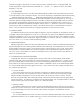
H. THE REAR PANEL
The Rear Panel contains all the Voyager’s connecitvity. In addition to the Audio Outputs, there
are the External Audio Input, Mixer Out/Filter In Insert jack, Accessory port CV/gate inputs and
outputs, the MIDI connectors, and the power connector.
POWER CONNECTOR: This is a standard AC power inlet, Use only a power cord designed to
mate with this receptacle. The Voyager power supply is designed to work with power inputs of
100-240 VAC; 50-60 Hz.
DANGER – Do not alter this connector in any way. Doing so can result in the risk of shock,
injury or death. Be familiar with the safety instructions printed at the beginning of this
manual. If the connector should be damaged, refer servicing to qualified personnel only.
OUTPUT MODE SWITCH: The Voyager Rack Mount’s outputs can be operated as either balanced
or unbalanced outputs. The Output Jacks are TRS, and in balanced output, provide an
electronically (non-transformer) balanced signal with a nominal output impedance of 600 Ω.
In unbalanced mode, the outputs are “Floating” TRS connections. Set this switch to its proper
position prior to power up, and do not change its position while the Voyager Rack Mount is
amplified.
LEFT/MONO and RIGHT OUTPUTS: The Outputs are ” TRS jacks. When connecting to an
unbalanced input, standard TS instrument cables can be used. When connecting to a balanced
input, use ” TRS to ” TRS cables for ” inputs, or ” TRS to male XLR cables for XLR inputs. With
just the Left/Mono output connected, both channels are summed to this output. Connect both
outputs for a stereo signal. In Dual Lowpass Mode, the Right output can be used by itself for
acheiving a single lowpass filter sound.
EXTERNAL AUDIO IN: This is an unbalanced ” input that accepts any instrument to line level
signal and routes it to the Mixer.
MIXER OUT/FILTER IN: This is a ” TRS jack that is used for inserting a processing device between
the Mixer and the Filters. The tip is the send and the ring is the return. See p. 18, figure 17 for a
block diagram.
MIDI CONNECTORS: These are connectors for MIDI in, out and thru.
ACCESSORY PORTS: These are two DB-25 connectors, for connecting the Voyager Rack Mount
to Expnsion accessories from Moog Music. The Outputs can be connected to a VX-351 Voyager
CV Expander. They are all the CV and Gate signals generated by the Voyager Rack Mount. The
Inputs can be connected to the forthcoming VX-352 Voyager CV Input Expander. The inputs
include Volume, Pan, Filter, Wave, Pitch, MOD1, MOD2, S+H In, S+H Gate, Release Switch, Env.
Gate, Env. Rate, LFO Sync, LFO Rate, as well as inputs for the programmable Touch Surface
Destinations.