
User Guide


43
1 Key Only (the first key pressed sounds)
3.4 TRIGGER MODES
TRIGGER MODES allows the user to select how the envelopes are triggered when more than one key
is pressed on the keyboard. Enter EDIT mode and use the +1 or –1 button to highlight TRIGGER MODES.
Press ENTER – the screen will display the current Trigger Mode. The +/- 1 button chooses a different
option. The choices are:
Single Trigger (legato, envelopes aren’t retriggered until keys are fully released)
Multi Trigger (each time a new note sounds, the envelopes are triggered)
4.1 FIL. A POLE SEL.
This allows the configuration of the cutoff slope of Filter A. Filter A is the Filter that is controlled only
by the cutoff control. In Dual lowpass it is the RIGHT output. In Highpass/Lowpass, it is the Lowpass filter.
Use the +/-1 buttons to select 1, 2, 3, or 4 poles. A pole = 6dB/ octave cutoff slope – as the poles
increase, so does the cutoff slope of the filter. a 1 pole filter has a 6 dB/ octave cutoff slope (when it’s
a lowpass filter you hear it as very bright) and a 4 pole filter has a 24 dB/ octave cutoff slope (when it’s
a lowpass filter you hear it as smooth, dark, yet warm).
4.2 FIL. B POLE SEL.
This allows the configuration of the cutoff slope of Filter B. Filter B is the Filter that is controlled by the
Cutoff control and the Spacing control. In Dual lowpass it is the Left output (using both outputs). In
Highpass/Lowpass, it is the Highpass filter. Use the +/-1 buttons to select 1, 2, 3, or 4 poles.
4.3 FILTER ENVELOPE GATE SOURCE
4.4 VOLUME ENVELOPE GATE SOURCE
With these two functions, gate sources other than the keyboard and the External Gate Input jack
can be programmed to trigger the Voyager’s two Envelope Generators when the Envelope Gate
switch is in the On/External Position. Possibilities include:
− Envelope Gate Input (default – this is “On” with nothing plugged into this jack)
− Touch Gate (The gate signal from the touch surface)
− S&H Gate (This is the LFO square wave with nothing plugged into the S&H Gate jack)
− MIDI Clock
− Keyboard Gate
− Gate is ON
− Gate is OFF
5.1 T.S. DESTINATION
Touch Surface Destination. What, you say? The Rack Mount Voyager has no Touch Surface. However,
there are CV/Gate inputs on the Accessory Port that can be programmed, just like the outputs of the
Touch Surface of the keyboard Voyager. Like the Voyager, when the Touch Surface Gate goes high,
the front panel controls for the T.S. destinations are turned off, and the X,Y, and A voltages determine
the values of the destinations. The forthcoming VX-352 will feature these inputs on 1/4” jacks.
Highlighting this item and pressing ENTER accesses a menu that shows the different outputs of the
Touch surface: X, Y, A, Gate. The screen looks like this:
Touch Surface X
Touch Surface Y
Touch Surface A
Touch Surface Gate
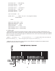
Use the +/- 1 button and selecting an output, then press ENTER. The display shows something like this:
Dest: Fil Cutoff
MIDI Ctrl. No. 19
Direction: Normal