FEB-24E UK SUPERCOMPACT COMBINATION BOILER USER MANUAL Morco Products Ltd Riverview Road, Beverley, East Yorkshire, HU17 0LD Telephone 01482 325456 Fax 01482 212869 1
CONTENTS Section Page 1 USERS INSTRUCTIONS 4 2 GENERAL SPECIFICATIONS 7 3 TECHNICAL DATA 9 4 GENERAL INSTALLATION REQUIREMENTS 10 5 INSTALLATION INSTRUCTIONS 13 6 COMMISSIONING INSTRUCTIONS 15 7 ROUTINE SERVING INSTRUCTIONS 16 8 TROUBLESHOOTING (SELF DIAGNOSTIC CODES) 3 17/18
1.- USERS INSTRUCTIONS GAS SAFETY (INSTALLATION AND USE) REGULATIONS 1998 (AS AMENDED) It is the law that all gas appliances are installed by a registered person, in accordance with the above regulations. Failure to install appliances correctly could lead to prosecution. It is in your own interest, and that of safety, to ensure that the law is complied with. Read these instructions carefully before attempting to operate the appliance. Comply with all applicable warnings.
USING THE PROGRAMMABLE CLOCK 1. Set the correct time by rotating the minute hand until the arrowhead points at the correct time on the 24 hour dial. 2. Check the position of the manual override switch (just to the bottom of the clock face). This has three positions: -Left: is ON overriding the timer mode -Middle is timer mode, with ON, OFF, times governed by the time clock. -Right position is OFF.
hot. DO NOT PLACE YOUR HANDS under the tap or use the shower until this initial flow has passed. - Allow time (30 seconds) for the temperature to stabilise after making an adjustment at the tap before making further adjustments. APPLIANCE SAFETY LOCK-OUT This boiler has a cut-out indicator built in to it.
A pre-winter check of the amount of antifreeze protection is strongly recommended. The level may have fallen due to leaks in the system requiring frequent refilling from the filling loop. 2.- GENERAL SPECIFICATIONS The Fagor FEB-24E is a wall hung, room sealed, fan assisted, microprocessor controlled fully modulating gas combination boiler for providing both central heating and domestic hot water. It is particularly suitable for Caravan Holiday Home and Park Home use.
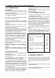
DIMENSIONS AND CONNECTIONS DETAILS 390 146 8 T.A. Ø100 9 7 128 50 25 195 85.5 60 65 6 100 5 4 1 3 2 680 705.8 651 1.- 3/4” BSP Central heating return 2.- Mains cable 3.-1/2” BSP Domestic cold water inlet 4.- 3/4” BSP Gas inlet 5.- 1/2” BSP D.H.W. outlet 6.- 3/4” BSP Central heating flow 8.- Pressure Relief Valve 9.- Draining valve for central heating T.A.:Room thermostat connection 1 12 9 FEB-24E 3 6 6 72 5 4 2 65 58 58 1 65 72 100 250 GAS GAZ ELECTRICAL CIRCUIT DIAGRAM 1.
3.- TECHNICAL DATA Model FEB-24EUK Category II2H3P Type Central heating and domestic hot water performances. C12,C 32,C 42,C 52,C 82,B22 Maximum output Minimum output kW 23.7 Btu/h 80,840 kW 7.6 Btu/h 26,151 Nominal central heating and domestic hot input (Gross) Maximum kW 28.9 Minimum kW 9.2 Nominal central heating and domestic hot water input (Nett) Maximum kW 26 Minimum kW 8.3 Domestic hot water flow rate at 25ºC (l/min) 13.6 Domestic hot water flow rate at 35ºC (l/min) 9.
4.- GENERAL INSTALLATION REQUIREMENTS 4.1 RECOMMENDATIONS - Ventilation requirements as stated in this manual must be observed. - Minimum clearance as stated in the technical data must be observed. FOR THE USER This appliance must be installed, adjusted or adapted for use with another type of gas, only by a qualified and competent person. Its quality and a correct installation will ensure that your heater works properly. 4.
4.4 VENTILATION REQUIREMENTS The following notes are for general guidance: - The Morco FEB-24E is a room sealed appliance and needs no purpose provided combustion air ventilation. - If the boiler is to be built into a small cupboard or compartment (i.e. at minimum clearances)and overheating can be forseen (i.e. close proximity to a cooking appliance etc) permanent air vents are recommended for cooling purposes in the cupboard or compartment .
- The following paragraphs outline the specifications of the items fitted to the boiler. - The DHW performance is summarised in the graph: Expansion vessel. D H W Performance graph The following table gives the maximum system volume that the integral 7 l expansion vessel can sustain under different temperature conditions. If the system volume exceeds that shown, an additional expansion vessel must be fitted and connected to the heating system primary return pipe as close as possible to the appliance.
5.- INSTALLATION INSTRUCTIONS 5.1 BOILER PACKAGING mostat is 24V (normally closed). Any 24V controls may be used, but gold contacts are recommended. The boilers are supplied in different packagings: DO NOT under any circumstances use a mains supply to the stat as you will blow the P.C.B. in the boiler. Only voltage free switching stats should be used. - Boiler - Flue system (separate packaging) 5.2 FITTING THE BOILER.
5.5 AIR/FLUE SYSTEM The standard flue kit supplied with the FEB-24E is a 1m horizontal coaxial air/flue kit as shown below. There are various other options available, including a vertical flue kit and other variations on the horizontal kit. Please ask for details. Never use a flue system which is not specifically approved for use with this appliance. The horizontal pipe may be cut down to the length required. The flue must be fitted with a .
6.- COMMISSIONING INSTRUCTIONS Before commissioning the appliance, the whole gas installation including the meter (if fitted) MUST be purged and tested for gas soundness. IMPORTANT: open all doors and windows, extinguish naked lights, and DO NOT SMOKE whilst purging the gas line. 6.3 GAS CIRCUIT Purge the gas circuit as described above. Turn on the gas cock to the installation and check that there are no leaks using leak detection fluid. 6.
(red pilot light). 6.7 USER’S INSTRUCTIONS To restart the boiler Set the main control on the position and then turn it back to the chosen position. The red indicator should go out. Upon completion of testing the system, the installer should: IMPORTANT: Whenever the boiler has been left idle for any length of time, or when a new gas bottle is installed (propane models), the appliance may switch off due to the presence of air in the pipes.
The cover is held in place by four spring clips and can be removed by grasping it at the top and pulling forward sharply to release. cold water inlet pipe BURNER PRESSURE Further access can be gained by removing the control panel. (Four screws), and moving down the electronic box. This is factory set, but should you suspect a problem proceed as follows: There is an easily accessible burner pressure nipple on the gas feed pipe, between the burner and the modulating gas valve.
EXAMPLES: Fault 4, P.C.B. failure, would display the following sequence of the red neon: 5 seconds 1 sec 1 sec 1 sec 1 sec 5 seconds N.B. The sequence repeats itself until either the reset button is depressed or the fault is rectified. Some faults require the component temperature to return to within operating range before reset. Also some faults may take up to 3 minutes before lockout is displayed. E.G. Fan failure/ water overheating.
MORCO PRODUCTS LTD, MORCO HOUSE, RIVERVIEW RD, BEVERLEY HU17 OLD TEL:01482 325456 FAX:01482 212869 EMAIL: SALES@MORCOPRODUCTS.CO.UK WEBSITE: WWW. MORCOPRODUCTS.CO.UK 20 24/06/05 N51J017F7 For more detailed servicing information, workshop manuals, technical advice, spare parts, product training, please phone us on 01482 325456 or contact us at the address below. Our qualified C.O.R.G.I. registered personnel are ready to help and advise you.