
Operation Manual


13
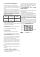
5.1 BOILER PACKAGING
The boilers are supplied in different packagings:
- Boiler
- Flue system (separate packaging)
5.2 FITTING THE BOILER.
- Decide where the boiler is to be fixed on the wall
taking into account the installation requirements
detailed in section 4.2 and the clearances and dimen-
sions described in the the technical data.
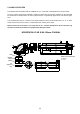
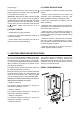
The centres for the hanging strap fixing are 85mm
below the top of the boiler casing, see fig below.
The flue pipe centre is 213mm above the hanging
strap centres. NOTE: a fall of about 2º - 3º should be
allowed on the flue pipe to stop water ingress into the
boiler.
A screw fixing should be made on the bottom rail of
the boiler to secure it during transport.
5.3 WIRING INSTRUCTIONS
Warning: observe the usual precautions to ensure
that the electricity supply is isolated before com-
mencing any installation or service work.
- The appliance is fitted with a 3 amp. fused 3 pin
plug for use with 230 V~50Hz. It should be fitted to a
shuttered socket outlet complying with BS 1363
WARNING: THIS APPLIANCE MUST BE
EARTHED.
ROOM THERMOSTAT:
This appliance may be used in conjunction with an
external room thermostat.
The voltage between the contacts of the room ther-
mostat is 24V (normally closed). Any 24V controls
may be used, but gold contacts are recommended.
DO NOT under any circumstances use a mains sup-
ply to the stat as you will blow the P.C.B. in the boil-
er. Only voltage free switching stats should be used.
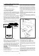
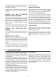
Connection of a room thermostat (optional).Proceed
as follows:
Unscrew the screw (A) as it shows figure 1, open
the bottom cover, where the connector of the room
thermostat is placed.
Press out the plastic disc (B) using a screwdriver to
form a hole so you can pass through the wires of the
room stat.
Replace cover.
The room thermostat must be installed on a wall
which is free from any objects and free from direct
contact with either sunlight or draughts.
5.4 WATER AND GAS CONNECTION
Connect the boiler up in such a way as to leave the
connecting pipes self supporting and free from any
stress.
Check that the gas pipe complies with the require-
ments of section 4.6
In order for the boiler to function correctly and to have
a long working life, the central heating system must
be properly designed, making sure that the temper-
ature difference between the flow and the return will
not be greater then 20°C.
5.- INSTALLATION INSTRUCTIONS
390
128 mm
85.5 mm
213.5 mm
FEB-24E
9
6
12
3
1
MOUNTING BRACKET
HOLE CENTRES
MINIMUM SIDE AND FRONT
CLEARANCE 5mm