
Operation Manual


8
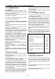
DIMENSIONS AND CONNECTIONS DETAILS
ELECTRICAL CIRCUIT DIAGRAM
1.- Surge arrestor
2.- Mains connection
3.- Earth
4.- Fan
5.- Pump
6.- Ignition
7.- Burner solenoid valve 1
8.- Burner solenoid valve 2
9.- Front panel control
10.- 3 way valve
11.- Air pressure switch
12.- Room stat (optional)
13.-Room stat connector block
14.- Clock connection
15.- Modulating solenoid valve
16.- Flame sensor
17.- High limit stat
21.- Hot water thermistor
22.- Central heating thermistor
23.- Pressure switch
25.- Burner functioning indicator
26.- Lock out indicator light
30.- Clock
S4 Gas change bridge. Made-
Propane. Break- Nat. Gas
P1 Maximum power adjustment
P2 Minimum Lighting pressure
P3 Output for central heating
adjustment
390
25
60
65
128
85.5
651
72
58
58
65
72
Ø100
65
100
250
705.8
146
GAZ
GAS
195
680
6 5 4 2 1
FEB-24E
9
6
12
3
1
6
5 4
3
1
8
7
2
9
50
100
1.- 3/4” BSP Central heating return
2.- Mains cable
3.-1/2” BSP Domestic cold water inlet
4.- 3/4” BSP Gas inlet
5.- 1/2” BSP D.H.W. outlet
6.- 3/4” BSP Central heating flow
8.- Pressure Relief Valve
9.- Draining valve for central heating
T.A.:Room thermostat connection
T.A.
17
26
25
S3
P3
P2
P1
FIL
2
3
1
5
6
7
8
101112
13
14
15
16
21
S1
S2
S4
22
MP
2
1
3
4
5
12
3
4
30
J10
J9
J8
J11
J4
J6
J1
J5
J19
J12
J2
4
23
9