FEB-24ED 3! USER INSTRUCTIONS AND TECHNICAL INSTRUCTIONS BOILER OUTPUT To Domestic Hot Water: Water: Minimum 7.7 kW (26,291.07 Btu/h) Maximum 24.5 kW (83,653.411 Btu/h) To Central Heating: Minimum 7.7 kW (26,291.07 Btu/h) Maximum 24.5 kW (83,653.411 Btu/h) EC-TYPE EXAMINATION CERTIFICATE 0099BU901 Morco House, Riverview Road, Beverley, East Yorkshire, HU17 0LD Morco Products Ltd Tel: 01482 325456 Fax: 01482 212869 Website: www.morcoproducts.co.
CONTENTS Section Page 1 USERS INSTRUCTIONS 4 2 GENERAL SPECIFICATIONS 8 3 TECHNICAL DATA 10 4 GENERAL INSTALLATION REQUIREMENTS 12 5 INSTALLATION INSTRUCTIONS 15 6 COMMISSIONING INSTRUCTIONS 17 7 ROUTINE SERVING INSTRUCTIONS 18 8 TROUBLESHOOTING 19 9 FAULT CODE TABLE 20 10 WARRANTY CONDITIONS 20 3
1.- USERS INSTRUCTIONS GAS SAFETY (INSTALLATION AND USE) REGULATIONS 1998 (AS AMENDED) It is the law that all gas appliances are installed by a registered person, in accordance with the above regulations. Failure to install appliances correctly could lead to prosecution. It is in your own interest, and that of safety, to ensure that the law is complied with. Read these instructions carefully before attempting to operate the appliance. Comply with all applicable warnings.
USING THE PROGRAMMABLE CLOCK 1. Set the correct time by rotating the minute hand until the arrowhead points at the correct time on the 24 hour dial. 2. Check the position of the manual override switch (just to the bottom of the clock face). This has three positions: -Left: is ON overriding the timer mode -Middle is timer mode, with ON, OFF, times governed by the time clock. -Right position is OFF.
- Caution: The boiler can produce water at over 70°C when in central heating mode. If you run a hot through the hot tap could be very tap when the boiler has been heating the radiators, the initial hot. DO NOT PLACE YOUR HANDS under the tap or use the shower until this initial has passed. - Allow time (30 seconds) for the temperature to stabilise after making an adjustment at the tap before making further adjustments. APPLIANCE SAFETY LOCK-OUT This boiler has a cut-out indicator built in to it.
PRECAUTIONS AGAINST FREEZING DURING WINTER STORAGE If the holiday home is to be un-occupied during cold periods, and whenever there is a threat of freezing, the domestic hot and cold water circuit must be drained as follows: -Turn off the cold water supply. -Open all hot and cold taps.
2.- GENERAL SPECIFICATIONS The Fagor MORCO FEB-24ED 3 is a wall hung, room sealed, fan assisted, microprocessor controlled fully modulating gas combination boiler for providing both central heating and domestic hot water. It is particularly suitable for Caravan Holiday Home and Park Home use. Maximum heat output in either heating or hot water mode is 23.7.kW (80.840 Btu/h), and priority is always given to the supply of hot water. Central heating expansion vessel. air pressure switch .
FEB-24ED 3 ELECTRICAL CIRCUIT DIAGRAM 1.- Mains connection 11.- Room Stat (optional) 2.- Earth 12.- Clock Connection 3.- Fan 13.- Modulating Solenoid Valve 4.- Pump 14.- Flame Sensor 5.- Ignition 15.- High limit stat 6.- Burner Solenoid valve 1 7.- Burner solenoid valve 2 17.- Central Heating return thermisthor 8.- Front panel control 18.- Pressure Switch 9.- 3 way valve 19.- External Probe 10.- Air pressure switch 20.
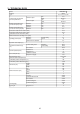
3.- TECHNICAL DATA FEB-24ED 3 ! Model Category II2H3P Type C12,C 32,C 42,C52,C 82,B22 kW Maximum output Btu/h Central heating and domestic hot water performances. kW Minimum output Btu/h 24.5 83,653.41 7.7 26,291.07 Nominal central heating and domestic hot input (Gr oss) Maximum kW Minimum kW 28.9 9.2 Nominal central heating and domestic hot water input (Nett) Maximum kW 25.5 Minimum kW 8.2 Domestic hot water flow rate at 25ºC (l/min) 14.
DIMENSIONS AND CONNECTIONS DETAILS T.A. 1.- 3/4” BSP Central heating return 2.- Mains cable 3.-1/2” BSP Domestic cold water inlet 4.- 3/4” BSP Gas inlet 5.- 1/2” BSP D.H.W. outlet 6.- 3/4” BSP Central heating flow 8.- Pressure Relief Valve 9.- Draining valve for central heating T.A.
4.- GENERAL INSTALLATION REQUIREMENTS 4.1 RECOMMENDATIONS - Ventilation requirements as stated in this manual must be observed. - Minimum clearance as stated in the technical data must be observed. FOR THE USER This appliance must be installed, adjusted or adapted for use with another type of gas, only by a qualified and competent person. Its quality and a correct installation will ensure that your heater works properly. 4.
4.4 VENTILATION REQUIREMENTS The following notes are for general guidance: - The Morco MORCO FEB-24ED 3! is a room sealed appliance and needs no purpose provided combustion air ventilation. - If the boiler is to be built into a small cupboard or compartment (i.e. at minimum clearances)and overheating can be forseen (i.e. close proximity to a cooking appliance etc) permanent air vents are recommended for cooling purposes in the cupboard or compartment .
Expansion vessel. The following table gives the maximum system volume that the integral 7 l expansion vessel can sustain under different temperature conditions. If the system volume exceeds that shown, an additional expansion vessel must be fitted and connected to the heating system primary return pipe as close as possible to the appliance. If an extra vessel is required, ensure that the total capacity of both vessels is adequate. If the pressure gauge indicates 2.
5.- INSTALLATION INSTRUCTIONS mostat is 24V (normally closed). Any 24V controls may be used, but gold contacts are recommended. 5.1 BOILER PACKAGING The boilers are supplied in different packagings: DO NOT under any circumstances use a mains supply to the stat as you will blow the P.C.B. in the boiler. Only voltage free switching stats should be used. - Boiler - Flue system (separate packaging) Connection of a room thermostat (optional) .
External Probe Curves 5.4 WATER AND GAS CONNECTION Connect the boiler up in such a way as to leave the connecting pipes self supporting and free from any stress. Check that the gas pipe complies with the requirements of section 4.6 In order for the boiler to function correctly and to have a long working life, the central heating system must be properly designed, making sure that the temperand the return will ature di erence between the not be greater then 20°C. 5.
6.- COMMISSIONING INSTRUCTIONS Before commissioning the appliance, the whole gas installation including the meter (if fitted) MUST be purged and tested for gas soundness. IMPORTANT: open all doors and windows, extinguish naked lights, and DO NOT SMOKE whilst purging the gas line. Before commencing the commissioning procedure, ensure that the central heating system and the domestic hot and cold water system have been flushed.
6.5.5 Appliance safety lock-out 6.7 USER’S INSTRUCTIONS If the boiler develops a fault the red LED will illuminate and the digital display shows the relevant fault code; see p19. Upon completion of testing the system, the installer should: To restart the boiler Set the main control on the position and then turn it back to the chosen position. The red LED should go out.
FAN CLEANING Remove the fan (3 screws) and using a soft brush remove any build up of debris from the fan blades. sure should increase slightly as the temperature rises. Finally check the filters which is situated in the cold water inlet pipe BURNER PRESSURE BURNER AND HEAT EXCHANGER INSPECTION AND CLEANING The front of the sealed air box must first be removed (8 screws) and care should be taken to avoid damaging the seal.
9.- FAULT CODE TABLE CODE F1 F2 FAULT Lack of gas or ignition problems Flame supervision failure Burner on but flame indicator off Minimum burner pressure too low F3 F4 Air pressure switch failure / Fan failure Water Pressure below 0.