
Operation Manual

15
5.1 BOILER PACKAGING
The boilers are supplied in dierent packagings:
- Boiler
- Flue system (separate packaging)
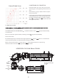
5.2 FITTING THE BOILER.
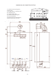
- Decide where the boiler is to be xed on the wall
taking into account the installation requirements
detailed in section 4.2 and the clearances and dimen-
sions described in the the technical data.
The centres for the hanging strap xing are 85mm
below the top of the boiler casing, see g below.
The ue pipe centre is 213mm above the hanging
strap centres. NOTE: a fall of about 2º - 3º should be
allowed on the ue pipe to stop water ingress into the
boiler.
A screw xing should be made on the bottom rail of
the boiler to secure it during transport.
5.3 WIRING INSTRUCTIONS
Warning: observe the usual precautions to ensure
that the electricity supply is isolated before com-
mencing any installation or service work.
- The appliance is tted with a 3 amp. fused 3 pin
plug for use with 230 V~50Hz. It should be tted to a
shuttered socket outlet complying with BS 1363
WARNING: THIS APPLIANCE MUST BE
EARTHED.
ROOM THERMOSTAT:
This appliance may be used in conjunction with an
external room thermostat.
The volt
age between the contacts of the room ther-
mostat is 24V (normally closed). Any 24V controls
may be used, but gold contacts are recommended.
DO NOT under any circumstances use a mains sup-
ply to the stat as you will blow the P.C.B. in the boil-
er. Only voltage free switching stats should be used.
Connection of a room thermostat (optional) .Proceed
as follows:
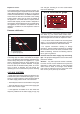
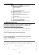
Unscrew the screw (A) as it shows gure 1, open
the bottom cover, where the connector of the room
thermostat is placed.
Press out the plastic disc (B) using a screwdriver to
form a hole so you can pass through the wires of the
room stat.
Replace cover.
The room thermostat must be installed on a wall
which is free from any objects and free from direct
contact with either sunlight or draughts.
External Probe connection Type 10K-25ºC, B3435
1% (25-85) (optional).
Press out the plastic disc (B) using a screwdriver to
form a hole so you can pass through the wires of the
external probe.
Conect the external probe wires to the free holes
with red wires in the other side..
Congurate the external
probe curve in instalation
menu.
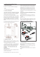
5.- INSTALLATION INSTRUCTIONS
Figure 1
A
B
1
2
3
Black
Wires
Thermostat
External Probe
TMV2
3