
Operation Manual

19
FAN CLEANING
Remove the fan (3 screws) and using a soft brush
remove any build up of debris from the fan blades.
BURNER AND HEAT EXCHANGER
INSPECTION AND CLEANING
The front of the sealed air box must first be removed
(8 screws) and care should be taken to avoid dam-
aging the seal. The combustion chamber cover can
then be removed (6 screws) and gas connections
taking care not to damage the delicate insulation
material inside.
Inspect the burner and heat exchanger fins for debris
and soot. Check also for rubbish below the burner.
IGNITION AND DETECTION ELEC-
TRODES
With the combustion chamber cover removed check
the condition of the electrodes for any sign of wear or
damage.
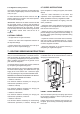
WATER CIRCUIT CHECKS
Inspect the pipe work inside the boiler for leaks.
Check that the pressure in the system is correct (0.8
to 1.6 bar).
Check the correct operation of the gauge. The pres-
sure should increase slightly as the temperature
rises. Finally check the filters which is situated in the
cold water inlet pipe
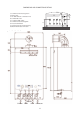
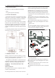
BURNER PRESSURE
This is factory set, but should you suspect a problem
proceed as follows: There is an easily accessible
burner pressure nipple on the gas feed pipe, between
the burner and the modulating gas valve.
The burner pressure nipple should give a reading of
35 mbar when the boiler is at full power on D.H.W.
mode. Remove the main cable plug to the gas valve
to get a minimum burner pressure reading which
should be 4,4 mbar.N.B. There is a logic program
built into the central heating enabling it to detect
when it is connected to a small system. This may pre-
vent the burner from firing on full (max press) so
ensure burner pressure is only tested in DHW mode.
FINAL CHECKS
Turn all the controls to their max position so that the
appliance begins to function. Check for gas leaks
using a suitable detector.
Check the boiler functions correctly in both central
heating and domestic hot water modes. The green
light will start flashing when the boiler is firing in either
mode. Check the amber LED iluminates when a
flame is detected in either central heating or domes-
tic hot water modes.
8.- TROUBLESHOOTING
COMMON PROBLEMS
1. Hot water temperature at the taps will be reduced, as the temperature of the mains cold water supply is
colder during the winter period.
2. The gas supply to the boiler has run out, or is about to run out, near empty propane gas bottles will supply
enough gas to run low power appliances such as cookers and gas fires, but will fail to supply high powered
appliances such as the combination boiler.
3. During busy periods, the mains cold water supply to the boiler may be subjected to variations in pressure,
this will result in fluctuations in the hot water temperature at the hot water outlet.
4. If the mains power supply to the boiler has been interrupted or turned off, then the time clock on the boil-
er must be reset to the correct time, if the boiler is to be operated in the timed sequence in central heating
mode.
The FEB-24ED 3! has a self diagnostic system built into its printed circuit board. Should a safety related,
or various other faults occur, then the boiler will failsafe by locking out, which is indicated by the red LED on
the control panel. The fault can be identified by the code in the digital display. The electronic failsafe is also
backed by a mechanical means of protection, should the electronics fail to detect a fault.
These mechanical forms of protection will protect and ensure the safe shut down of the boiler. The software
protection built into the P.C.B. will run a system check on components which are essential to the safe
operation of the boiler. This occurs before any ignition sequence takes place, if any component is found to be
faulty or out of a predetermined range, the boiler will lockout with the fault code displayed on the digital
screen.
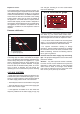
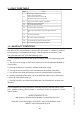
FAULT CODES:
When the Boiler detects a fault, you could identify the fault looking at the display of the
boiler. Each Fault will begin with the F letter and continious with a number. For example:
This is fault 2 (F2), Air pressure switch/ Fan failure. NOTE: The red LED stays on
constantly.