
Operating Instructions and Installation Instructions

20
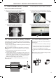
section 5 - installation instructions
Note.
A 5º or 14º pitched roof plate (not supplied) is required before
proceeding with the installation of this kit.
This kit is suitable for both 5º and 14º pitched roof terminations,
usingaconcentricuetorunverticallyfromthetopoftheboilerand
terminating above roof level.
Connection to the top of the boiler is made using a vertical connector
(supplied in the kit - RSF346).
WEATHER PROOFING
Wheretheuepassesthroughtherooflineanadequatesealmustbe
made. This is achieved by using a suitable sealant.
ACCESSORIES
FlueDuctExtensionKitsareavailableforuelengthsextending
beyond 1m. These packs contain 1m extension ducts and may be
cut to the desired length. If 90º elbows are used (RSF315) they will
reduce the overall height by 1m per elbow.
5.14
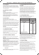
Terminal Position Minimum Dimension
Directly below an opening,
air brick, windows, etc. 300 mm
Below plastic / painted gutters 300 mm
Painted surface 300 mm
Below eaves or balcony 500 mm
Below velux windows 2000mm
Above or side of velux windows 600mm
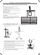
5.15
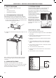
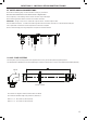
ASSEMBLING THE ROOF FLUE KIT
1. Positiontheroofplate(suppliedseparately)overtheholecutintheroofandinsertue
terminal from the roof end.
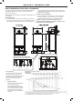
5º & 14º
MAX LENGTH:
7.5m**
**minus any
90º bends
MIN LENGTH:
0.950m
BOILER
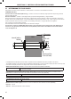
2. Ensure that if the length needs to be adjusted to allow an additional 30mm added to
theouterairtubelength14mmaddedtotheinneruelength.Thisallowscorrect
engagement into the vertical connector.
Note. Ensure a square cut. remove all burrs and sharp edges.
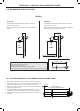
3. Fit the vertical connector (supplied in the kit) and secure the vertical connector by
applying downward pressure on the connector.
4. Positiontheclamponthetopfaceoftheuemanifoldandpushithorizontally
backwards.Locatebothclamplugsintotheuemanifoldandsecuretotheue
manifold clamp with the M5 retaining screw.
5. “Push” assembly A into vertical connector.
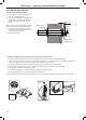
Notes. Ensure turret sample points are servicable and all caps and plugs are tted.
Ensure condensate siphon/trap is lled with water.
6. Finally ensure the roof plate is correctly sealed to the roof.
Flue Terminal
RSF050
14º
RSF050
5º
1
ASSEMBLY A
Assembly A
5
3
Vertical
connector
4