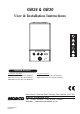
GB24 & GB30 User & Installation Instructions off e max reset mode min preheat min max status burner preheat GB24 BOILER OUTPUT To Domestic Hot Water: To Central Heating: GB24/30 Minimum 8.0 kW (27,296 Btu/h) GB24 Maximum 24.2 kW (82,570 Btu/h) GB30 Maximum 30.3 kW (103,384 Btu/h) GB24/30 Minimum 8.0 kW (27,296 Btu/h) GB24/30 Maximum 24.2 kW (82,570 Btu/h) Morco House, Riverview Road, Beverley, East Yorkshire, HU17 0LD Morco Products Ltd Tel: 01482 325456 Fax: 01482 212869 Website: www.
Morco GB24 & GB30 Destination Country: Combination Boiler BE = Belgium CH = Switzerland CZ = Czech Republic ES = Spain FR = France GB = UK GR = Greece IE = Ireland IT = Italy NL = Netherlands PL = Poland PT = Portugal SI = Slovenia
Contents SECTION PAGE 1 Users Instructions...........................................................................................................................................4 2 General Specifications....................................................................................................................................8 3 Technical Data................................................................................................................................................
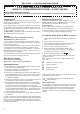
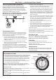
SECTION 1 - USERS InstrucTIons For any queries pleAse ring the MORCO consumer helpline : 01482 325456 NOTE. BOILER RESET PROCEDURE To reset boiler, turn mode control knob to reset position and immediately turn knob back to required setting. Introduction Minimum Clearances Due to the high efficiency of the boiler, condensate is produced from the flue gases and this is drained to a suitable disposal point through a plastic waste pipe at the base of the boiler.
SECTION 1 - USERS InstrucTIons To shut down the boiler Operation Set the mode knob control to OFF Winter conditions - i.e. CH and DHW required. Ensure the mode knob control (A) is set to winter ( To relight the boiler ) Repeat the procedure detailed in ‘To light the boiler’. The boiler will fire and supply heat to the radiators but will give priority to DHW on demand.
SECTION 1 - USERS InstrucTIons Loss of system water pressure The pressure gauge indicates the central heating system pressure. If the pressure is seen to fall below the original installation pressure of 1-2 bar over a period of time then a water leak may be indicated. In this event re-pressurise the boiler. If unable to do so or if the pressure continues to drop a Gas Safe Registered Engineer, or in other countries a qualified and competent Gas Installer should be consulted.
SECTION 1 - USERS InstrucTIons Points for the BOILER User Note. In line with our current warranty policy we would ask that you check through the Troubleshooting guide to identify any problems external to the boiler prior to requesting a service engineers visit. Should the problem be found to be other than with the appliance we reserve the right to levy a charge for the visit, or for any pre-arranged visit where access is not gained by the engineer.
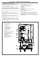
SECTION 2 - gENERAL SPECIFICATIONS 2.1 General Specifications The boiler contains the following components: The Morco GB range of boilers are wall mounted, full sequence, automatic spark ignition low water content, fanned flue, high efficiency condensing combination boilers.
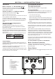
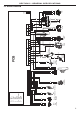
r bk Water Flow Turbine b bk p bk r bk Flow Return Water pressure Thermistor Thermistor Switch or X8 X6 X5 X7 Service Connector b bk p bk y Fan 11 10 9 8 7 6 5 4 3 2 1 6 5 4 3 2 1 4 3 2 1 5 4 3 2 1 KEY b - blue bk - black br - brown r - red p - pink y - yellow w - white y/g - yellow/green g - grey or - orange v - violet b br y/g bk bk 8 7 Flame Sensor Electrode y/g 9 5 br 4 Spark Electrode b X3 y/g y/g 6 PCB bk 2 1 b Spark Generator 3 5 bk 3 X2 Gas Valve
section 3 - TECHNICAL DATA Table 1 - General Data Morco GB 24 30 Gas supply I3p - G31 - 37mbar Gas Supply Connection 15mm copper compression Injector Size (mm) 3.75 3.
section 3 - TECHNICAL DATA boiler dimensions, services & clearances The boiler connections are made on the boiler bulkhead fittings. The following minimum clearances must be maintained for operation and servicing. Additional space will be required for installation, depending upon site conditions. Side and Rear Flue a. Provided that the flue hole is cut accurately, e.g.
SECTION 4 - general installation requirements 4.1 Recommendations Compartment Installations Current Gas Safety (Installation and Use) Regulation or Rules in Force. A compartment used to enclose the boiler should be designed and constructed specially for this purpose. The boiler is suitable only for installation in the specified countries and should be installed in accordance with the rules in force. An existing cupboard or compartment may be used, provided that it is modified for the purpose.
SECTION 4 - general installation requirements 4.4 Air Supply It is NOT necessary to have a purpose provided air vent in the room or internal space in which the boiler is installed. Neither is it necessary to ventilate a cupboard or compartment in which the boiler is installed, due to the low surface temperature of the boiler casing during operation. 4.5 Electrical Supply Warning This appliance MUST be earthed.
section 5 - installation Instructions 5.1 Boiler Packaging 5.4 internal wiring The boilers are supplied in different packagings: The boiler has been pre-fitted with a 3 amp fused approved moulded 3 pin and flying lead for use with 230V 50Hz. • Boiler • Flue System (separate) • Hardware Pack (separate) 5.2 Fitting/Mounting the Boiler Decide where the boiler is to be fixed on the wall, taking into account installation requirements detailed in previous section. 1.
section 5 - installation Instructions 5.5 Water and Gas ConnectionS Ensure all boss blanking plugs are removed before making any connections. Each valve must be fitted to the correct boss as shown in diagram below Do not subject any of the isolating valves to heat as the seals may be damaged. Ensure that the green fibre washer is used on the CH flow connection. IMPORTANT - The gas service cock is sealed with a top hat washer - DO NOT subject to heat.
section 5 - installation Instructions 5.7 dETERMINING THE fLUE lENGTH IMPORTANT. The boiler must be installed in a vertical position in accordance to the installation instructions. Standard Flue Kits Horizontal Flue Terminal RSF303 (600mm long) - contains: Flue turret, non telescopic single piece flue incorporating a terminal and inner rubber wall seal. Extension Kit RSF341 - contains: 1 metre length of flue pipe (Functional length 950mm), 1 support bracket.
section 5 - installation Instructions 5.8 DETERMINING THE FLUE LENGTH figure 1 REAR FLUE SIDE FLUE Cut flue length = distance from edge of turret to outside of wall dimension A + 47mm. Cut flue length = distance from edge of turret to outside of wall dimension B + 47mm. Note. Minimum dimension A which can be accommodated is 91mm. Note. Minimum dimension B which can be accommodated is 136mm (with minimum clearance of 2.5mm). B A WALL WALL SIDE Fit to wall REAR Fit to wall Minimum clearance 2.
section 5 - installation Instructions 5.10 Installing the flue Fitting Flue Through the Wall 1. Ensure the seam and the outlet terminal are at the top and fitted as shown. 2. Once the flue is installed it is IMPORTANT that the white air duct protrudes from the aluminium spinning at least 17mm. Note. If less than 50% of the length of the flue is internal the flue should be fitted from outside. 3.
section 5 - installation Instructions 5.11 fLUE eXTENSIONS (RSF341) - OPTIONAL for side outlet refer to section 1.2 before connecting. Inner Pipe Assembly Instructions 1. Make sure that ‘top hat’ on the collar (A) fits over the rectangular form on the inner plastic pipe (B). A 3. Slide the pipe and collar assembly back into the outer housing (E), note that this can only be done at the female end of the outer housing. B Top Hat E Rectangular 4.
section 5 - installation Instructions 5.14 Fitting the Optional Roof Flue Kit (RSF345) (Pitched) Note. A 5º or 14º pitched roof plate (not supplied) is required before proceeding with the installation of this kit. This kit is suitable for both 5º and 14º pitched roof terminations, using a concentric flue to run vertically from the top of the boiler and terminating above roof level. Connection to the top of the boiler is made using a separately supplied vertical connector (RSF346).
section 5 - installation Instructions 5.16 Condensate Drain Condensate Drain Condensate Drain 137 156 This appliance is fitted with a siphonic 75mm sealed condensate trap system that requires filling before operating the appliance for the 1st time or after maintenance. All condensate pipework should conform to the following: a.
section 5 - installation Instructions Condensate drain - Cont’d.......
SECTION 6 - COMMISSIONING INSTRUCTIONS Before commissioning the boiler, the whole gas installation including the meter (if fitted) MUST be purged and tested for gas soundness. Purge air from the gas installation by the approved methods only. WARNING. Whilst effecting the required gas soundness test and purging air from the gas installation, open all windows and doors, extinguish naked lights and DO NOT smoke. Ensure that the flue has been installed correctly and no vents are blocked.
SECTION 6 - COMMISSIONING INSTRUCTIONS THE DISPLAY The user control has one neon and one display to inform the user about the status. The display will show the status of the boiler. The neon will show the status of the flame. If no flame is detected the neon is off. When the flame is detected the neon will be lit permanently. Below is a list with display function in normal operation. 0 Standby, no demand for heat present. Boiler is active for central heating. Boiler is active for domestic hot water.
SECTION 7 - RoutinE Servicing Instructions 7.1 servicing schedule For the very latest copy of literature for specification, maintenance practices and parts replacement, visit our website www.morcoproducts.co.uk where you will be able to download the relevant information. Warning. Always turn off the gas supply at the gas service cock, and switch OFF and disconnect the electricity supply to the appliance before servicing.
SECTION 7 - RoutinE Servicing Instructions 7.2 boiler Upper & Lower front panel removal / Replacement REMOVAL REPLACEMENT 1. Lift the lower front panel access panel. 4. Hook the upper panel onto the top retaining clips. 2. Unscrew the two fixing screws, close the access panel to retain the two screws and hinge the lower front panel down into the service position. 5. Retain the upper panel with the two fixing screws previously removed ensuring a good seal is made. 6.
SECTION 7 - RoutinE Servicing Instructions 7.4 burner removal and cleaning 1. Ensure the sump is fully drained 3 2. Undo the two screws and remove the sump cover retaining the lower flue manifold. 2 2 3. Lift the manifold to clear the bottom sealing gasket and remove manifold. 4. Remove the 2 burner front fixing screws and loosen the 2 rear extended nuts by at least ten turns. 5. Lift off the burner from the combustion chamber. To facilitate the removal angle the burner as shown.
SECTION 7 - RoutinE Servicing Instructions 7.6 cleaning the heat exchanger Note: Ensure the condensate trap/siphon is fully drained before cleaning. Refer to Frames 7.5. 1 Ignition Electrode Flame Detection 1. Remove ignition and flame detection electrodes. Refer to Frames 7.9 & 7.10. 2. It is advisable to replace the sump cover prior to the water flush process. 3. Thoroughly flush the heat exchanger by pouring water into the top of the combustion chamber ensuring the full top area is covered. 4.
SECTION 7 - RoutinE Servicing Instructions 7.8 burner REMOVAL 1. Refer to Frame 7.3. 3 2. Undo the two screws and remove the sump cover. 3. Lift the manifold to clear the bottom sealing gasket and remove manifold. 2 2 4. Remove the 2 front fixing screws and loosen the 2 rear extended nuts. 4. Lift off the burner from the combustion chamber. To facilitate the removal angle the burner as shown. 5. Fit the new burner, replacing any damaged or deteriorating sealing gasket. 4 6.
SECTION 7 - RoutinE Servicing Instructions 7.10 flame detection electrode 1. Remove the burner. Refer to Frame 7.8. 2. Check dimensions are correct as in diagram below. 3. Reassemble in reverse order. Flame Detection Electrode FOR REMOVAL: 1. Unplug the ignition lead and remove the earth lead. 2. Remove the 2 retaining screws and remove the electrode. 3. Reassemble in reverse order replacing the gasket if necessary. e dg te h aig Str mm .5 12 7.
SECTION 8 - fACT SHEETS 8 fact sheets There are a number of detailed fact sheets available for users to download from Morco’s website. Please visit www.morcoproducts.co.
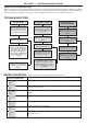
SECTION 9 - fault codes 9 fault codes DISPLAY CODE ON BOILER DESCRIPTION ACTION Outside Sensor Failure Reset the appliance - if the boiler fails to operate then please contact Morco (if under warranty) or alternatively a Gas Safe Registered Engineer, or in other countries a qualified and competent Gas Installer if outside of the warranty period. Low Mains Voltage Contact a qualified electrician or your electricity provider. Unconfigured PCB Unconfigured PCB.
SECTION 10 - COMBUSTION CHECK FLOWCHART FOR CO LEVEL AND COMBUSTION RATIO CHECK ON COMMISSIONING A CONDENSING BOILER Important Preliminary Information on Checks The air gas ratio valve is factory-set and must not be adjusted DURING COMMISSIONING. PRIOR TO CO LEVEL AND COMBUSTION RATIO CHECK The installation instructions must have been followed, gas type verified and gas supply pressure / gas rate checked as required prior to commissioning.
SECTION 10 - COMBUSTION CHECK Start Set Boiler to Maximum Gas Rate In accordance with boiler instructions, (by fully turning on hot tap) set boiler to operate at maximum rate (full load condition). Allow sufficient time for combustion to stabilise. Note. Do not insert analyser probe during this period to avoid possible flooding of sensor. Carry Out Flue Integrity Check Using Analyser Insert analyser probe into air inlet test point (where available) and allow readings to stabilise. Note.
SECTION 11 - WARRANTY WARRANTY CONDITIONS The boiler is guaranteed against manufacturing defects for a period of two years from the date of first commissioning. However the guarantee is subject to proof of commissioning in accordance with the Gas Safety (Installation and Use) act 1998. The guarantee does NOT cover the following issues: 1. Frost damage to any part of the boiler containing water during freezing conditions. 2. The removal of sludge or hard water scale due to lack of antifreeze/inhibitor 3.