REMOTE METER TM Installation and Operation Manual …. Digital Remote Meter for Monitoring System Performance …. Version: RM-1 1098 Washington Crossing Road Washington Crossing, PA 18977 USA www.morningstarcorp.
REMOTE METER DIMENSIONS In Wall Mount Frame Mount inches (mm) 2
Contents 1.0 Important Safety Instructions ..........................................................................................4 2.0 General Information ..........................................................................................................5 3.0 Installation .........................................................................................................................6 3.1 Frame Mount ........................................................................................
1.0 Important Safety Instructions SAVE THESE INSTRUCTIONS: This manual contains important safety, installation and operating instructions for the Morningstar Remote Meter. The following symbols are used throughout this manual to indicate potentially dangerous conditions or important safety instructions. WARNING: Indicates a potentially dangerous condition. Use extreme caution when performing this task. CAUTION: Indicates a critical procedure for safe and proper operation of the controller.
2.0 General Information Thank you for selecting the Morningstar Remote Meter (RM-1) digital display. The RM-1 is an accessory for compatible Morningstar controllers and inverters. The meter features a large 4-digit display and custom icons. The RM-1 provides comprehensive system information including voltage, current, and temperature. A Status LED indicates charging progress and controller operating state.
3.0 Installation The RM-1 can be added to a compatible Morningstar controller or inverter when it is first installed, or at anytime after the controller or inverter has been in service. The meter can be mounted in two ways: Frame Mount or In Wall Mount. A plastic mounting frame is included for Frame Mount installations. 3.1 Frame Mount Mount the RM-1 on a surface using the plastic mounting frame (included). No cut-outs in the surface are required except for four (4) screw holes.
Step 1 Place the mounting frame against the wall or mounting surface in the desired location. Use a level to level the frame. Step 2 Hold the leveled mounting frame in place on the wall with one hand. Place one of the #8 1-3/4” screws into a screw hole on the frame. Lightly tap the screw head with a hammer to mark the hole location. Repeat for the remaining three (3) screw holes.
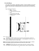
3.2 In Wall Mount The In Wall mount method is a low-profile installation. The RM-1 faceplate sits flush with the mounting surface and the body of the meter rests in a hole cut-out in the mounting surface. The meter wiring is concealed behind the mounting surface or the interior of the wall. Tools and Materials Required: 9 drill 9 philips screwdriver 9 3” hole saw (75 mm hole saw) 9 level 9 3/32” Drill bit (2.35 mm bit) 9 (4) #8 x ¾” screws (included) 9 safety glasses Figure 2.
meter location if necessary. Step 2 Using a drill and 3” (75 mm or 76 mm) hole saw, cut a hole centered on the mark on the surface from step 1. Don’t forget to wear safety glasses! Step 3 Insert the RM-1 body into the hole cut-out in the surface. Level the meter faceplate. Using a pencil or pen, mark the location of the four (4) mounting holes. Step 4 Remove the meter from the cut-out. Using a drill and 3/32” drill bit, drill a 1” deep pilot hole at each of the four (4) marks.
4.0 Operation 4.1 Meter Menu System information is arranged in rows as shown in the example meter menu in figure 3 below. Each row contains information related to a specific input or output (Solar, Battery, Load, etc). Use the “L” and “R” arrow buttons to view each screen in a row of information. After navigating to the last screen in a row, another advance in the same direction returns the user to the first screen of the row. Each row of information is stacked vertically.
4.2 Buttons The RM-1 has three (3) buttons for meter menu navigation as shown in figure 4. Each press of the center “C” button advances down to the next row of information. Another push of the “C” button on the last row returns to the top row. Use the “L” and “R” arrow buttons to navigate to each display screen in a row of information. Figure 4. Meter buttons 4.
NOTE: if a controller has two solar, battery, or load connections, the “2” icon along with the appropriate icon indicates the second of the two connections. Options / Settings Indicator – The wrench options icon is displayed when the meter options menu is in use. See section 4.4 for more information. Error Indicator – The error icon flashes when a controller error exists. Self Diagnostics Indicator – Indicates that self diagnostics is in progress. 4.
Backlight Timer: During normal operation, a press of any meter button turns on the backlight. The backlight timer specifies how long the backlight shall remain on after the last button press.
5.0 Trouble shooting There is no display. 9 Verify that the Morningstar controller or inverter connected to the RM-1 is powered and working properly. The meter is supplied power from the connected controller or inverter. 9 Disconnect and reconnect the meter cable RJ-11 connection. Press firmly until there is a “click”. 9 There may be a break in the meter cable. Inspect the cable for frays or pinches. The LCD display is dim. 9 Check the system battery voltage.
6.0 Limited Warranty The Remote Meter is warranted to be free from defects in material and workmanship for a period of FIVE (5) years from the date of shipment to the original end user. Morningstar will, at its option, repair or replace any such defective products. CLAIM PROCEDURE Before requesting warranty service, check the Operator’s Manual to be certain that there is a problem with the meter. Return the defective product to your authorized Morningstar distributor with shipping charges prepaid.
7.0 Technical Specifications ELECTRICAL • • Self-consumption Backlight off Backlight on Minimum Operating Voltage 6 mA 15 mA 8V MECHANICAL • • • • Connector type Faceplate dimensions Faceplate material Frame dimensions • • • • • • Frame material Surface mount screws In Wall mount screws Meter cable Meter cable temp. rating Meter weight RJ-11 (6 pin) 95.3 x 95.3 mm / 3.75 x 3.75 in Powder coated steel 114.3 x 114.3 x 34.54 mm / 4.5 x 4.5 x 1.