TRISTAR Digital Meter 2 Installation and Operation Manual 8 Pheasant Run Newtown, PA 18940 USA email: info@morningstarcorp.com www.morningstarcorp.
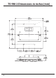
TS-RM-2 Dimensions in inches [mm] 2
TABLE OF CONTENTS 1.0 Important Safety Instructions 2.0 Meter Description 4 6 3.0 Installation 9 9 2.1 Meter Versions 2.2 General Use 3.1 3.2 3.3 3.4 3.5 General Information TS-M-2 TS-RM-2 TS-M-2-600V Multi-TriStar Network Set-Up 7 8 11 13 14 16 4.0 Operation 23 5.0 Trouble-Shooting 42 6.0 Warranty 7.0 Technical Specifications 45 46 TriStar Meter 2 Operator’s Manual 3 4.1 Backlighting 4.2 Single TriStar System 4.3 TriStar MeterBus Networks 5.1 Trouble-Shooting Steps 5.
1.0 Important Safety Instructions SAVE THESE INSTRUCTIONS This manual contains important safety, installation and operating instructions for the TriStar Meter 2, TriStar Remote Meter 2 and TriStar Meter 2-600V digital displays. The following symbols are used throughout this manual to indicate potentially dangerous conditions or to mark important safety instructions: WARNING: Indicates a potentially dangerous condition. Use extreme caution when performing this task.
Installation Safety Precautions (Local Meters) • Disconnect all power sources from the controller before mounting TS-M-2 or TS-M-2-600V local meters. • Use the supplied RJ-11 meter cable to connect the meter to the controller. • Bend the power conductors in the conduit wiring box so that they do not touch the back of the meter. • Apply silicon gel to the RJ-11 connections on the meter and the controller for maximum protection from corrosion.
2.0 Meter Description TriStar controllers are technically advanced and professional solar battery chargers and load controllers. Three digital LCD meters with identical displays are available for the TriStar family of controllers. Two versions mount on a controller; the other is mounted in a remote location.
• Connections are by standard RJ-11 6-position modular plugs • 5-year standard warranty 2.1 Meter Versions This manual covers three standard versions of a digital LCD meter that can be used with the TriStar family of solar controllers. Version TS-M-2: This local meter is provided as an assembly that replaces the TriStar front access cover. The TS-M-2 meter mounts to the TriStar controller case. Version TS-RM-2: This remote meter is provided with a mounting plate and 30m (98.4 ft) of cable.
2.2 General Use TriStar digital meters can display a great deal of information about the TriStar controller and the operation of your system. In addition, the meters facilitate manual programming and controller diagnostics. Familiarity with these capabilities will increase your confidence that the system is working properly, and will help maximize system reliability / performance and battery life. The organization of the display screens is described in Section 4.0.
3.0 Installation The TriStar meters can be added to the controller when it is first installed, or at anytime after the controller has been in service. 3.1 General Information ! CAUTION: Risk of Shock Disconnect all power to the TriStar prior to installation. The meter will not be damaged if connected with power, but for safety, power should be disconnected before the access cover is removed.
For Systems with Two or More TriStar Controllers: • Use a meter or MSView PC software to adjust the MeterBus address of each TriStar controller in the system. • Mount a local meter (TS-M-2 or TS-M-2-600V) to a TriStar, or mount a TS-RM-2 in a remote location. • Connect the meter(s) and controllers to a HUB-1 (sold separately) • Adjust the meter settings NOTE: A TriStar meter may be connected to each TriStar in a multi-TriStar system without the use of a HUB-1.
3.2 TS-M-2 Install (1 TriStar) To install the local controller-mounted meter to a single TriStar: 1. Use a large phillips screwdriver to remove the four wiring box cover (standard or extended) screws. 2. Connect the supplied RJ-11 cable to the meter and to the RJ-11 socket on the TriStar. Looking at the back of the meter, connect to the left RJ-11 socket. NOTE: If the cable is connected to the wrong RJ-11 meter socket, there will not be any damage and the LCD display will remain blank.
Figure 3-1.
3.3 TS-RM-2 Install (1 TriStar) The remote meter is designed to mount into a standard duplex (2-gang) box, or flush against a wall or cabinet with a properly sized hole. To install the remotely mounted meter to a single TriStar: 1. Connect one end of the 30 meter cable to the TriStar RJ-11 socket (or to the open meter socket if a TS-M-2 or TS-M-2-600V is already mounted to the TriStar). 2. Looking at the back of the remote meter, connect the other end of the cable to the left socket - see Figure 3.
3.4 TS-M-2-600V Install (1 TriStar) To install the local controller-mounted meter to a single TriStar MPPT 600V: 1. Use a large phillips screwdriver to remove the four wiring box cover (standard or extended) screws. 2. Use a 7mm nut-driver to remove the existing blank meter panel. Retain the (4) nuts. 3. Position the TS-M-2-600V mounting plate onto the screws behind the meter window, and secure using the (4) nuts retained in Step 2. 4.
Figure 3-2.
3.5 Multi-TriStar Network Set-Up Multiple TriStar controllers can be networked together using a Morningstar MeterBus Communication Hub (HUB-1) and RJ-11 cables. Networking controllers together on a MeterBus network allows one or more TriStar digital meters to communicate with all controllers on the network. This enables the display of total system data on the meter. Additionally, each individual controller’s data may be viewed in separate menus.
Modify the MeterBus Address with the TriStar Meter 2 1. Connect a TriStar local or remote meter to the second TriStar in the system. 2. Wait for the meter to power up and detect the connected TriStar. Once the meter has fully started, scroll to the bottom of the main menu to the Logged Data screen. Press and hold the down push-button for three seconds until the Advanced Set-Up menu appears. See the Advanced Set-Up menu topic in section 4.2 for more details on how to access this menu. 3.
Modify the MeterBus Address using MSView PC Software Morningstar’s MSView PC software is available at no charge at morningstarcorp.com\tech support\software library. Download the latest version and install it. Then follow these steps to change a MeterBus address: 1. Open MSView, and in the Tools menu, select the set-up wizard for your model of TriStar controller. 2. If custom settings are already programmed, read the settings out first and then edit them.
Step 2 - MeterBus Network Connections After all TriStar controllers have been programmed with unique MeterBus addresses, the controllers must be networked together using one or more MeterBus Communication Hubs (HUB-1). Be careful not to overload a single TriStar in the system with too many meters, hubs, or other MeterBus devices. If the system will have multiple meters, wire each meter to a different TriStar. If possible, do not connect a meter to the same TriStar that provides power to the hub(s).
Example Network #1 1 TS-RM-2 TriStar MEETERHUB MeterBus Communication Hub FOR USE WITH MORNINGSTAR METERBUS NETWORKS ONLY MODEL: HUB-1 FOR INDOOR USE ONLY 2 TriStar Figure 3-3. A simple two TriStar system with Remote Meter. • TriStar 1 provides power to both a hub and to a single Remote Meter connected to Output Power Port A. • TriStar 2 is connected to Port 1 on the Hub and is electrically isolated from TriStar 1.
Example Network #2 TriStar 1 TS-RM-2 TriStar 600V with TS-M-2-600V TriStar 2 Relay Driver 3 Figure 3-4. A medium-sized network with 3 TriStars, 2 meters, and a Relay Driver. • TriStar 1 provides power to the hub and Remote Meter. • TriStar 2 powers the Relay Driver and TriStar 3 powers the Local Meter. It is good practice to distribute the network meters and Relay Driver as shown to avoid loading a single TriStar with all of the network accessories.
Example Network #3 2 1 Link Out X 3 MEETERHUB MeterBus Communication Hub 4 Link In FOR USE WITH MORNINGSTAR METERBUS NETWORKS ONLY Y MODEL: HUB-1 FOR INDOOR USE ONLY 5 6 7 MEETERHUB MeterBus Communication Hub 8 Link Out FOR USE WITH MORNINGSTAR METERBUS NETWORKS ONLY Z MODEL: HUB-1 FOR INDOOR USE ONLY 9 10 MEETERHUB MeterBus Communication Hub 11 FOR USE WITH MORNINGSTAR METERBUS NETWORKS ONLY MODEL: HUB-1 FOR INDOOR USE ONLY 12 13 TriStar Figure 3-4.
4.0 Operation The four push-buttons are in the shape of directional arrows. Changing a display screen will be in the direction of the arrow (up or down, left or right). The information displayed and the organization of the meter screens differs depending on the number of TriStar controllers connected to the meter. The exact menu structure for each supported controller is provided on separate meter maps included with the TS-M-2, TS-RM-2 and TS-M-2-600V meters.
4.1 Backlighting The first push of any of the four meter push-buttons will turn on the backlight. The backlight will remain on for 5 minutes from the last button press. NOTE: When turning on the backlight, there is no change in the display. The second press of any push-button will then change the display screen. This applies to TS-M-2, TS-RM-2 and TS-M-2-600V meter versions. NOTE: Only one meter will be backlit at a time.
4.2 Single TriStar System The following section describes the TS-M-2, TS-RM-2 and TS-M-2-600V meter operation in systems with one or more meters connected to a single TriStar controller. See section 4.3 for information pertaining to meters connected in multiTriStar MeterBus networks. Start-Up Displays When the meter is plugged in and powered on, a sequence of start-up screens will be displayed.
Operating Displays Operating Display screens show the general operating information for the controller and cumulative information collected over time. These display screens are configured in a continuous circular loop and can be quickly accessed by scrolling either left or right. The number of Operating Displays and the exact information displayed in each screen varies depending on the TriStar controller model and mode of operation (charge, load, diversion, etc).
Manual Operations Screens located below the Operating Displays provide for various resets and manual functions. Additional display screens for resets and manual functions can be found in the Diagnostics menu. Figure 4-3 shows the location of the Manual Operation displays in the menu.
Equalize Start/Stop Use this screen to initiate and terminate a manual equalization charge. Holding the right arrow for 2 seconds will start the equalization charge. Hold again for 2 seconds and equalization will stop. The SOC LEDs on the TriStar controller should flash the equalize start/stop sequence as defined in the controller Operator’s Manual.
Reset Total Amp-hours (Diagnostics Menu) This display will reset the total Ah and total kWh counters to zero. These values are normally not reset. However, if a new battery is installed for example, the owner may wish to reset these counters.
Diagnostics Menu The Diagnostics menu lists faults, alarms, and technical diagnostic information about the controller. This information may be useful for trouble-shooting problems with the controller or solar system. Operating Display Operating Display Operating Display Manual Operation Display Manual Operation Display Diagnositics (Press ) TriStar Settings (Press ) Logged Data (Press ) Advanced Setup (Press ) ( to Return) Diagnostics Faults: NONE Alarms: NONE Battery --- C 54.13V 23.
meter map for the particular model purchased for detailed display information. Faults & Alarms If a “Fault” or “Alarm” condition flashes on one of the main Operating Displays, navigate down to the Diagnostics Menu for a list of existing faults or alarms. The faults and alarms lists are always displayed on the first 2 screens of the Diagnostics Menu. Use the left and right push-buttons to scroll through each list of faults and alarms, if any exist.
TriStar Settings Menu The TriStar Settings menu provides the following functions: • confirms the setup and settings switches (DIP switches) are configured correctly • provides hardware and software version numbers for technical support • screens to select a language or change the units of temperature values on the meter Operating Display Operating Display Operating Display Manual Operation Display Manual Operation Display Diagnositics (Press ) TriStar Settings (Press ) Logged Data (Press ) Advanc
Information Displayed The first display screen shows the TriStar controller’s hardware and software revision as well as the controller serial number. These numbers are helpful if technical support is required. The second display screen provides the meter hardware and software version. Following the version displays is a list of screens that provide specific information describing the operating mode and charging / load settings.
Logged Data Menu NOTE: Not all TriStar models support data logging or viewing logged data on the TriStar Meter 2. Refer to the meter map of the particular model purchased for detailed display information or consult the controller Operator’s Manual. The Logged Data menu displays select operating data that has been collected and stored in the TriStar controller’s internal memory. The structure of the Logged Data menu is shown in Figure 4-6.
Advanced Set-Up Menu NOTE: Not all TriStar models support Advanced Set-Up on the TriStar Meter 2. Refer to the meter map of the particular model purchased for detailed display information or consult the controller Operator’s Manual. The Advanced Set-Up menu allows the user to modify certain operating settings. To enter the Advanced Set-Up menu, scroll down to the last display screen in the main menu. Press and hold the down push-button for 3 seconds. The Advanced Set-Up entry display will appear.
The setting values displayed in the Advanced Set-Up menu screens vary depending on the TriStar controller model and mode of operation (charge, load, diversion, etc). Refer to the meter map of the particular model purchased for detailed display information. If a meter and TriStar PWM controller have been updated with current firmware, MeterBus addresses can be assigned via the meter. Address programming can also be done through Morningstar’s MSView PC software.
4.3 TriStar MeterBus Networks The following section describes the additional meter screens displayed on the TS-M-2, TS-RM-2, and TS-M-2-600V in systems with two or more TriStar controllers on a MeterBus network. Section 4.2 covers the individual controller menus. Start-Up Displays When the meter is plugged in and powered on, a sequence of start-up screens will be displayed. Figure 4-8 below shows the start-up sequence and provides a description of the information displayed on each screen.
Network Device List The Network Device List is a top level menu that contains a screen for each controller on the network. There is also an additional “SYSTEM” screen that provides system-wide information. An example Network Device List is shown in figure 4-9 below. The example system has two controllers: a charge controller and a TS-45 in Load Control mode. System System Information Menu TS-MPPT-45-150V Charge (01) TS-45 Load (02) TS-MPPT-45-150V Information Menu TS-45 Information Menu Figure 4-9.
System Information Menu The System Information menu displays the following: • Operating Displays show aggregate system data • Manual Operation screens for system-wide control • System Settings menu to adjust meter settings System Operating Display Controller #1 Top Menu Controller #X Top Menu Operating Display Operating Display Reset Ah (Hold 2sec) Equalize START (Hold 2 sec) Turn Load OFF (Hold 2 sec) System Settings (Press ) ( to Return) System Settings Meter Version v01.01.
System Operating Displays The quantity and type of Operating Displays in the System Information menu depends on the controllers in the system. If one or more charge controllers are in the system, the Operating Displays in Figure 4-11 will be included in the Operating Displays list. Battery Temperature Battery Voltage Total System Charging Watts 50.4V 2243W 23C 44.5A CHRG Total System Charge Current Battery Temperature Battery Voltage Total System Charging Amp-hours 50.4V 23C 160.7Ah 44.
Battery Temperature Battery Voltage Total System Diversion Watts 50.4V 227W 23C 4.5A DIV Total System Diversion Current Battery Temperature Battery Voltage Total System Diversion Amp-hours 50.4V 23C 5.0Ah 4.5A DIV Total System Diversion Current Figure 4-13. Total system diversion Operating Displays System Manual Operation Displays Display screens located below the Operating Displays provide for various resets and manual functions. These commands are broadcast across the network to all controllers.
5.0 Trouble-Shooting The TriStar Meter 2 displays data transmitted digitally from the TriStar controller(s). There should not be any conflicts between the values displayed on the meter and information collected from the controller through other communication interfaces. For this reason, the meter trouble-shooting focuses on mechanical and electrical issues with the meter and meter connection. 5.
The meter map provided does not match the meter display: • the meter map may not match the meter display due to software revisions, the latest maps are available for download on our website • if there are substantial differences between the map and the display, either the wrong map is used or the controller is not configured for the correct operating mode The meter does not respond to button pushes: • • • • press the push-button down harder - it will not break try other push-buttons to confirm one or mor
5.2 RJ-11 Cable Repair The meter connecting cable is a standard 6-conductor telephone cable with RJ-11 modular connectors. If the cable or connectors are damaged, they can either be repaired or replaced. A standard flat 6-wire phone cable should be used. With the RJ-11 connectors, the cable assembly appears as shown in figure 5-1. 1 1 Figure 5-1. Meter cable assembly A 4-wire cable can also be used for shorter distances.
6.0 Warranty The TriStar Meter 2 is warranted to be free from defects in material and workmanship for a period of FIVE (5) years from the date of shipment to the original end user. Morningstar will, at its option, repair or replace any such defective products. CLAIM PROCEDURE Before requesting warranty service, check the Operator’s Manual to be certain that there is a fault with the TriStar Meter 2. Return the defective product to your authorized Morningstar distributor with shipping charges prepaid.
7.0 Technical Specifications Electrical Self-consumption 7.5 mA (not backlit) 42.5 mA (with backlighting) Mechanical Remote mounting plate dimensions 116 x 116 mm (4.56 x 4.56 in.) Plate material Powder-coated steel Meter weight 0.23 kg / 0.5 lb TS-M-2 0.18 kg / 0.4 lb TS-RM-2 0.18 kg / 0.4 lb TS-M-2-600V Connector type RJ-11 (6-pin) TS-M-2 cable 0.13 m / 5 in - 6 conductor TS-RM-2 cable 30 m / 98.4 ft - 6 conductor TS-M-2-600V cable 0.