
150V Ground Fault Protection Device Installation and Operation Manual

11
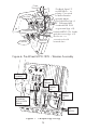
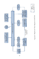
Step 3. Crimp the supplied ring terminals on the
breaker side ends of the (+) and (-) breaker<->controller
conductors. Connect breaker side (+) wire to post (1)
(line side), and breaker side (-) wire to post (3) (load
side) using the supplied hardware (see Figure 6).
Step 4. Connect controller side breaker<->controller
wires to controller (+) and (-) solar terminal lugs. Close
GFPD-150V breakers.
Step 5. Run the supplied (+) and (-) GFPD power ter-
minal wires through a convenient knock-out for connec-
tion to voltage source described in Step 9.
Step 6. Position and fasten GFPD-150V / Breaker
assembly into place in the GFPD-150V box.
Step 7. Run (+) and (-) controller<->battery wires
through right knock-out, and connect to controller’s (+)
and (-) battery terminal lugs.
Step 8. Wire battery (+) through battery disconnect to
battery (+) terminal, and connect. Connect battery (-)
wire to battery (-) terminal.
Step 9. Using supplied in-line fuse holder and 5A fuse,
install fuse 6 to 12 in. from (+) battery terminal.
Connect (+) and (-) wires from GFPD-150V to external
10-72V source (usually system battery) (+) and (-) termi-
nals.
NOTE: Do not tap from a lower voltage battery
bank section that is part of a higher voltage bank -
an imbalance will occur.
WARNING: The PV system must be properly grounded
AVERTISSEMENT: Le système PV doit être correcte-
ment mise à la terre.
Step 10. Ground the PV system properly by electrically
connecting each individual metallic component such as
PV frames, conduit, combiner boxes, controllers, invert-
ers, GFDIs, and any other dead metal to Earth ground.
Locate the system ground on the battery side at either
a battery (+) or battery (-) terminal depending on sys-
tem polarity. Install the grounding system in accor-
dance with local codes and regulations.
Step 11. Close battery disconnect switch.
Step 12. Close solar disconnect switch.