
Remote Temperature Sensor Manual

ProStar Temperature Sensor Installation Instructions
NOTE:
The ProStar circuits are static sensitive. Be sure to touch a metallic
grounded object to discharge built-up static charge on your body before
touching the circuits.
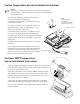
Remove the 4 Phillips screws in the corners of the 1.
heat sink and remove the plastic case.
Pull about 3 inches(80mm) of the probe wire through 2.
the heat sink as shown.
Solder a sensor wire into each of the two holes at 3.
J12(see drawing). There is no polarity(+ or -), so
either wire can go into either hole.
Carefully replace the plastic case. Make sure all 4.
4 corners of the heat sink are fl at against the case
mounting posts. If the sensor wire interferes with the
assembly, push or pull the wire slightly to clear the
interference.
Replace the 4 case screws. DO NOT over-tighten 5.
the screws.
The temperature sensor should be located next to 6.
the battery. For best results, insulate the temperature
sensor from surrounding air so that only the tem-
perature of the battery is measured. (note: DO NOT
place the sensor inside the battery cell)
J12 Connection Point
Temperature Sensor Lug
Tools:
Phillips Screwdriver
Soldering Iron
(recommended 20 Watt,
small tip: about 250 C)
ProStar with
case removed
SunSaver MPPT Temperature
Sensor Installation Instructions
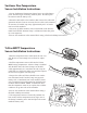
Secure the Remote Temperature Sensor lug to one of the battery 1.
posts. The RTS lug is electrically isolated. (note: DO NOT place
the sensor inside the battery cell)
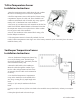
Route the RTS cable to the SunSaver MPPT. Protect the cable 2.
with grommets and wire loom as necessary. Excess cable can be
trimmed as necessary. If needed, strip away approximately 0.25”
of insulation from each conductor.
Insert one (1) RTS conductor into each terminal on the RTS 3.
terminal block as illustrated. Note that polarity is not important.
Secure the conductors in the terminal block using a small fl at 4.
head screwdriver