
Remote Temperature Sensor Manual

TriStar Temperature Sensor
Installation Instructions
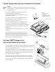
Run the temperature sensor cable down the wire conduit. 1.
Be sure to feed enough wire to allow for adjustments.
Pull the temperature sensor cable into the TriStar wiring 2.
compartment. Inspect the cable end. There should be two
conductors with tinned ends. If needed, strip away approxi-
mately 0.25” of insulation from each conductor.
Insert one (1) conductor into each terminal on the dual ter-3.
minal block labeled “REM. TEMP” as illustrated. Note that
the temperature sensor is not a polar device. Either conduc-
tor can go into each of the terminals.
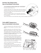
Secure the conductors in the terminal block using a fl at 4.
head or Philips screwdriver.
The temperature sensor is electrically isolated. For best 5.
results, bolt the temperature sensor lug to one of the battery terminals. (note: DO NOT place the sensor
inside the battery cell)
SunKeeper Temperature Sensor
Installation Instructions
Secure the Remote Temperature Sensor lug 1.
to one of the battery posts. The RTS lug is
electrically isolated. (note: DO NOT place the
sensor inside the battery cell)
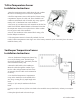
Route the RTS cable to the SunKeeper. 2.
Route the cable through the conduit or pro-
tect the cable with grommets and wire loom
as necessary. Excess cable can be trimmed as
necessary.
Cut the blue Temperature Compensation 3.
Loop on the SunKeeper in the middle of the
wire loop, creating two (2) equal length wire
leads.
Strip ½” (13 mm) of insulation off all wire 4.
leads.
Crimp or splice the two (2) blue wire leads to the two RTS wires (red & black). Polarity is not impor-5.
tant.
Wrap the spliced ends in electrical tape.6.
v07 October 2009