
SunSaver Manual

3.0 INSTALLATION INSTRUCTIONS
20
WARM AIR
COOL AIR
AT LEAST
2” (51 mm)
AT LEAST
2” (51 mm)
SEALED
OR
FLOODED
SELECT
LOAD
BATTERY
SOLAR
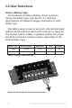
Remove
Jumper
Wire for
Flooded
Battery
{
12 V
BATTERY STATUSTEMP. SENSORCHARGING STATUS
!
See Operator’s
Manual
Nominal Rating
12 Volts dc
Max. Input 30 V
Solar 20.0 A
Battery 20.0 A
Load 20.0 A
Max. Ambient 65 ºC
indoor use only
Use 75 ºC Copper
Conductors Only
CONFORMS TO ISA 12.12.01
CERTIFIED TO CAN/CSA STD
C22.2 NO.213-1992
Class I, Division 2
Groups A,B,C,D
Hazardous Loc.
Temp. Code: T5
RoHS
MORNINGSTAR
S S
20L
UN AVER-
SOLAR CONTROLLER SS-20L-12V
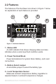
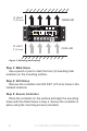
Figure 3. Mounting and cooling.
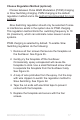
Step 3: Mark Holes
Use a pencil or pen to mark the four (4) mounting hole
locations on the mounting surface.
Step 4: Drill Holes
Remove the controller and drill 3/32” (2.5 mm) holes in the
marked locations.
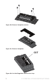
Step 5: Secure Controller
Place the controller on the surface and align the mounting
holes with the drilled holes in step 4. Secure the controller in
place using the mounting screws (included).