
SunLight SL-10L-12V Installation


8. For safety and the most effective lightning protection, the nega-
tive conductor of the battery should be properly grounded. The
SunLight connects the PV-negative, Battery-negative and Load-
negative internally per UL recommendations. No switching is
done in the negative current path.
7.0 OPERATION
7.1 S
ELECT
L
IGHTING
C
ONTROL
O
PTION
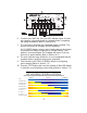
After completing the system connections, select the desired
LIGHTING CONTROL option. Refer to Section 4.0 for a sum-
mary of the SunLight’s ten standard options for lighting control.
A brief description follows below:
OFF Lights remain turned off
2,4,6,8,10 Hours light is turned on after sundown
3/1, 4/2, 6/2
Light is turned on after sundown, turned off
during the night, and turned on again one hour
(3/1) or two hours (4/2, 6/2) before sunrise
D/D Dusk-to-Dawn, light is on all night
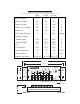
To select a lighting option, turn the rotary digital switch to the
desired position. An arrow in the rotary switch will point to the
selected position. This is a digital switch, so it will click into
each of the ten positions.
To confirm correct selection of the desired control option, press
the TEST button located below the rotary switch (see Section
7.2 below).
7.2 T
EST
B
UTTON
Press the TEST button until a distinct click is heard and felt.
This button performs two functions:
a. Confirm rotary switch selection
To verify that the rotary digital switch is set at the desired position,
press the TEST button. The red LED will flash once per second.
Count these LED flashes to confirm the correct switch setting.
Each of the 10 LIGHTING CONTROL positions has a unique
number of flashes. These are as follows:
8