
TriStar Manual


21TriStar MPPT Operator’s Manual
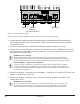
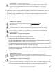
Step 5 - Remote Temperature Sensor
The included Remote Temperature Sensor (RTS) is recommended for effective temperature com-
pensated charging. Connect the RTS to the 2-position terminal located between the battery (+)
terminallugandtheLEDstack(seegure2-1).TheRTSissuppliedwith33ft(10m)of22AWG
(0.34 mm
2
) cable. There is no polarity, so either wire (+ or -) can be connected to either screw
terminal. The RTS cable may be pulled through conduit along with the power wires. Tighten the
connector screws to 5 in-lb (0.56 Nm) of torque. Separate installation instructions are provided
inside the RTS bag.
CAUTION:
The TriStar MPPT 150V will not temperature compensate charging parameters if the RTS is not
used.
CAUTION: Equipment Damage
Never place the temperature sensor inside a battery cell. Both the RTS and the battery will be
damaged.
NOTE:
The RTS cable may be shortened if the full length is not needed. Be sure to reinstall the ferrite
choke on the end of the RTS if a length of cable is removed. This choke ensures compliance with
electromagnetic emissions standards.
PRUDENCE :
Le TriStar MPPT 150V ne compense pas la température des paramètres de charges si le RTS
n’est pas utilisé.
PRUDENCE : Endommagement de l’équipement
Ne placez jamais la sonde de température dans un élément de batterie. Le RTS et la batterie
seraient endommagés.
REMARQUE :
Le câble de RTS peut être raccourci si la totalité de la longueur n’est pas nécessaire. Assurez-
vous de réinstaller la bobine en ferrite sur l’extrémité du RTS si une longueur de câble est
enlevée. Cette bobine assure la conformité avec les normes d’émissions électromagnétiques.